Section 2
DESCRIPTION
11
cepting stated pressures.
START - 0 TO 50 PSIG (0 TO 3.5 BAR)
When the compressor START button is depressed,
the sump pressure will quickly rise from 0 to 50 psig
(0 to 3.5 bar). During this period both the pressure
regulator and the solenoid valve areclosed, the inlet
valve is fully open due to inlet air flow, and the com-
pressor pumps at full rated capacity. The risingcom-
pressor air pressure is isolated from the service line
in this phase by the minimum pressure valve, set at
approximately 50 psig (3.5 bar).
NORMAL OPERATING MODE - 50 TO 115 PSIG
(3.5 TO 7.9 BAR )
When the pressure air rises above 50 psig (3.5 bar),
the minimum pressure/check valveopensanddeliv-
ers compressed air to the service line. From this
point on, the line air pressure is continually moni-
tored by a line pressure gauge and a pressure
switch usually set at 125 psig (8.6 bar). The pres-
sure regulator and the solenoid valve remain closed
during this phase. The inlet valve remains fully open
for maximum capacity.
MODULATING MODE - 115 TO 125 PSIG (7.9 TO
8.6 BAR)
If less than the rated capacity of compressed air is
being used, the service line pressure will rise above
115 psig (7.9 bar). The pressure regulator valve
gradually opens, applying air pressure through the
control line to the inlet valve piston. This causes the
inlet valve to partially close reducing the amount of
air entering the compressor until it matches the
amount of air being used. The control system func-
tions continually in this manner, between the limits
of 115 to 125 psig (7.9 to 8.6 bar), in response to
varying demands from the service line.
The pressure regulator has an orifice which vents a
small amount of air to the atmosphere when the
pressure regulator controls the inlet valve. The ori-
fice also bleeds any accumulated moisture from the
control lines.
UNLOAD - IN EXCESS OF 125 PSIG (8.6 BAR)
LINE PRESSURE
When no air is being used,the service line pressure
rises to the setting (cut--out pressure) of the pres-
sure switch. the pressure switch opens, interrupting
the electrical power to the solenoid valve. At this
time, the solenoid valve allows dry sump tank air
pressure or service air pressure through a shuttle
valve to be applied directly to the inlet valve piston
and keep it closed. Simultaneously, the solenoid
valve sends a pneumatic signal to the blowdown
valve. The blowdown valve opens the sump to the
compressor intake reducing the sump pressure to
approximately 25 to 27 psig (1.7to 1.9 bar). The
check valve in the air service line pressure prevents
line pressure from returning to the sump.
Whenthe linepressure drops to thelowsetting(cut--
in pressure) of the pressure switch (usually 115 psig
[7.9 bar]), the pressure switch closes, re--energizing
the 3--way solenoid valve and allowing the blow-
down valve to close. The re--energized solenoid
valve again prevents pressure from reaching the in-
let valve. The inlet valve is fully open and the com-
pressor delivers full rated capacity. Should the pres-
sure begin to rise,the pressureregulator willresume
its normal function as previously described.
To accommodate varied periods of time when there
are not any air requirements, “Dual--Control” is uti-
lized. This feature allows you to set the compressor
in an automatic position whereby the compressor
will shut down when no compressed air requirement
is present and restart as compressed air is needed.
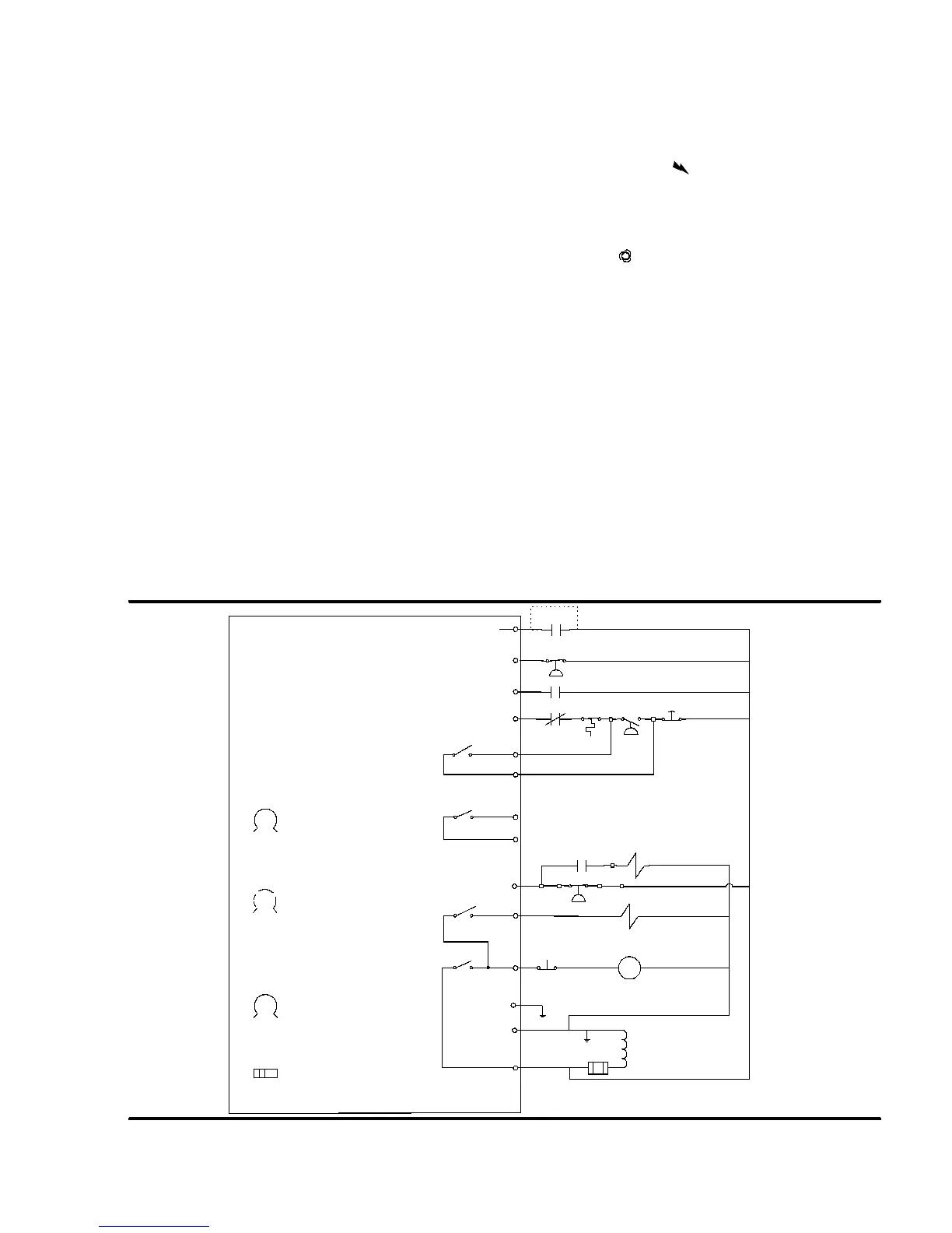
2.7 CONTROL SYSTEM, FUNCTIONAL DE-
SCRIPTION- SUPERVISOR II
Refer t o F igur e 2 -- 4. T he pur pos e of t he c ompr es s or
Control System is to regulatethe amount of air being
compressed to match theamount of compressed air
beingused.TheCapacity control system consists of
a
solenoid valve
,
regulator valve
and an
inlet
valve
. The functional description of the Control Sys-
tem is described below in four distinct phases of op-
eration. The following description text applies to all
LS--10 Series compressors with optional Supervisor
II. For explanatory purposes, this description will ap-
ply to a compressor with an operating range of 100
to 110 psig (6.9 to 7.6 bar). A compressor with any
other pressure range would operate in the same
manner except stated pressures.
START MODE - 0 TO 50 PSIG (0 TO 3.5 BAR)
When the compressor
“I” (START)
pad is de-
pressed, the sump pressure will quickly rise from 0
to 50 psig (0 -- 3.4 bar). The compressor initially
starts unloaded, then switches to full load when full
rpm has been achieved. During this period, both the
pressure regulator and the solenoid valve are
closed, the inlet valve is fully open and the compres-
sor pumps at fullrated capacity. The rising compres-
sor air pressure is isolated from the service line in
this phase by the minimum pressure valve set at
approximately 50 psig (3.4 bar).
FULL LOAD MODE - 50 TO 100 PSIG (3.4 TO 6.9
BAR)
When the compressed air pressure rises above 50
psig (3.4 bar), the minimum pressure valve opens
allowing compressed air to flow into the service line.
From this point on, the lineair pressure is continually
monitored by the Supervisor. The pressure regula-
tor and the solenoid valve remain closed during this
phase. The inlet valve is in the fully open position as
long as the compressor is running at 100 psig ( 6.9
bar) or below.
MODULATING MODE -- 100 TO 110 PSIG (6.9 TO
7.6 BAR)
If less than the rated capacity of compressed air is
being used, the service line pressure will rise above
100 psig (6.9 bar). The pressure regulator valve
gradually opens, directing air pressure to the inlet
 Loading...