Section 4
INSTALLATION
21
4.1 MOUNTING OF COMPRESSOR
A foundation or mounting capable of supporting the
weight of the compressor, and rigid enough to main-
tain the compressor frame level and the compressor
in alignment is required. The compressor frame
must be leveled and secured with foundation bolts,
and full uniform contact must be maintained be-
tween the frame and foundation. No piping loads
shall be transmitted to the compressor at the exter-
nal connections.
4.2 VENTILATION AND COOLING
For air--cooled compressors, select a location to
permit sufficient unobstructed air flowing in and out
to the compressor to keep the operating tempera-
ture stable. The minimum distance that the com-
pressor should be from surrounding walls is three
(3) feet (1m). To preventexcessive ambient temper-
ature rise, it is imperative to provide adequate ven-
tilation.
For water--cooled compressors, it is necessary to
check the cooling water supply. The water system
mus t be c apable of s upply ing the f lows s hown in
Table I -- Water Supply R equir ements ( Water --
cooled), and must be maintained at all times. These
figures apply to a compressor running at full load
with an aftercooler. For cooler water or a partially
loaded compressor, slightly less water is required.
However, for hotter water the flow requirements are
significantly greater.
Table 2 -- Ventilation Requir ements indic ates t he
ventilation requirements necessary to keep the
compressor running at a normal operating tempera-
ture. The fan air requirement is the volume of air
which must flow through the compressor for proper
ventilation. The specifiedheat rejection requirement
is the amount of heat that is radiated by the com-
pressor.This heat must beremoved to assure a nor-
mal operating temperature. With air--cooled com-
pressors it is possible to use this heat for space
heating, providing no additional pressure drop is
created across the fan. Consult a Sullair office for
assistance in utilizing this heat.
DO NOT
install a water--cooled or an air--cooled/af-
tercooled compressor where it will be exposed to
temperatures less than 32
_
F(0
_
C).
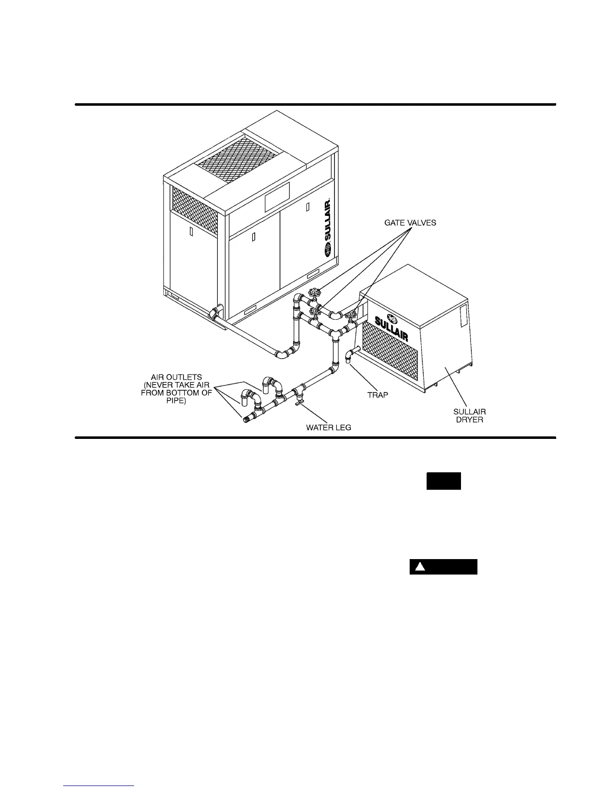
4.3 SERVICE AIR PIPING
Service air piping should be installed as shown in
F igur e 4 -- 1. A s hut -- off v alv e s hould be ins talled t o
isolate the compressor from the service line if re-
quired. Also notice that the service line should be
equipped with water legs and condensate drains
throughout the system.
WARNING
!
“The Plastic Pipe Institute recommends against the
use of thermoplastic pipe to transport compressed
air or other compressed gases in exposed above
ground locations, e.g. in exposed plant piping.” (I)
Sullube should not be used with PVC piping sys-
tems. It may affect thebond at cemented joints. Cer-
tain other plastic materials may also be affected.
(I) Plastic Pipe Institute, Recommendation B,
Adopted January 19, 1972.
(I)
Water pressure should be between 25 and 75 psig/ 1.7 and 5.2 bar.
TABLE 1--WATER SUPPLY REQUIREMENTS (WATER--COOLED)
WATER FLOW (I)
WATER TEMP. GPM/ LPM
0
_
F/
_
C 25HP/ 18KW 30HP/ 22KW 40HP/ 30KW
70/ 21 3.75/ 14.2 4.50 /17.0 5.75/ 21.8
80/ 26.6 5.00/ 18.9 6.00/ 22.7 7.50 /28.4
Cooling Type Air-cooled with Aftercooler Water-cooled
Motor HP/KW 25/18 30/22 40/30 25/18 30/22 30/40
Fan Air CFM 2500/4250 2500/4250 3500/5950 720/1220 720/1220 720/1220
M
3
/Hr
(II)
Ventilating Air/
Heat Rejection
BTU/Hour 76980/ 88800/ 118320/ 8500/ 10000/ 13000
KCal/Hour 19500 22500 29900 2150 2550 3300
Cooling Water/
Heat Rejection
BTU/Hour 76980/ 88800/ 118320/
Kcal/Hour 19500 22500 29900
(II)
Applies to compressor with canopy only (vent fan).
(I)
Values based on: 100% RH, 85
_
F/ 29
_
C Ambient
TABLE 2--VENTILATION REQUIREMENTS (I)
 Loading...

