Section 2
DESCRIPTION
6
warranty.
Fluid is injected into the compressor unit at each
stage, and mixes directly with the air as the rotors
turn, compressing the air. The fluid flow has three
main functions:
• As coolant, it controls the rise of air temper-
ature normally associated with the heat of
compression.
• Seals between the rotors and the stator and
also between the rotors themselves.
• Acts as a lubricating film between the rotors
allowing one rotor to directly drive the other,
which is an idler.
After the air/fluid mixture is discharged from the
compressor unit, the fluid is separated from the air.
At this time, the air flows to the service line and the
fluid is cooled in preparation for reinjection.
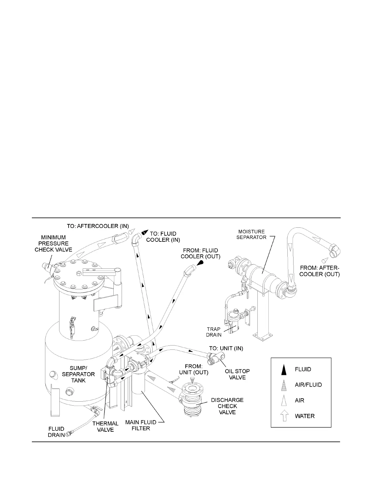
2.4 COMPRESSOR COOLING AND LUBRICATION
SYSTEM, FUNCTIONAL DESCRIPTION
Refer to Figures 2-2, 2-3A and 2-3B. The cooling
and lubrication system consists of a fluid cooler,
aftercooler, full flow fluid filters, fluid stop valve,
thermal valve and interconnection piping. For
water-cooled models, a shell and tube fluid cooler
and aftercooler are mounted on the compressor
package. For air-cooled models, they are radiator-
type coolers, and are mounted on the compressor
package.
The pressure in the receiver/sump causes fluid flow
by forcing the fluid from the high pressure area of
the sump to an area of lower pressure in the com-
pressor unit.
Fluid flows from the bottom of the receiver/sump to
the thermal valve. The thermal valve bypass is fully
open when the discharge temperature is below
220ºF (104.4ºC). The fluid passes through the ther-
mal valve, the main fluid filter and directly to the
compressor unit, thus feeding the bearings, seals
and rotor area.
As the discharge temperature rises above 220ºF
(104.4ºC), due to the heat of compression, the
Figure 2-2 Compressor Cooling, Lubrication and Discharge System
 Loading...