Section 6
MAINTENANCE
42
12. Check the return line strainer before restarting
the compressor (replacement strainer P/N
02250117-782).
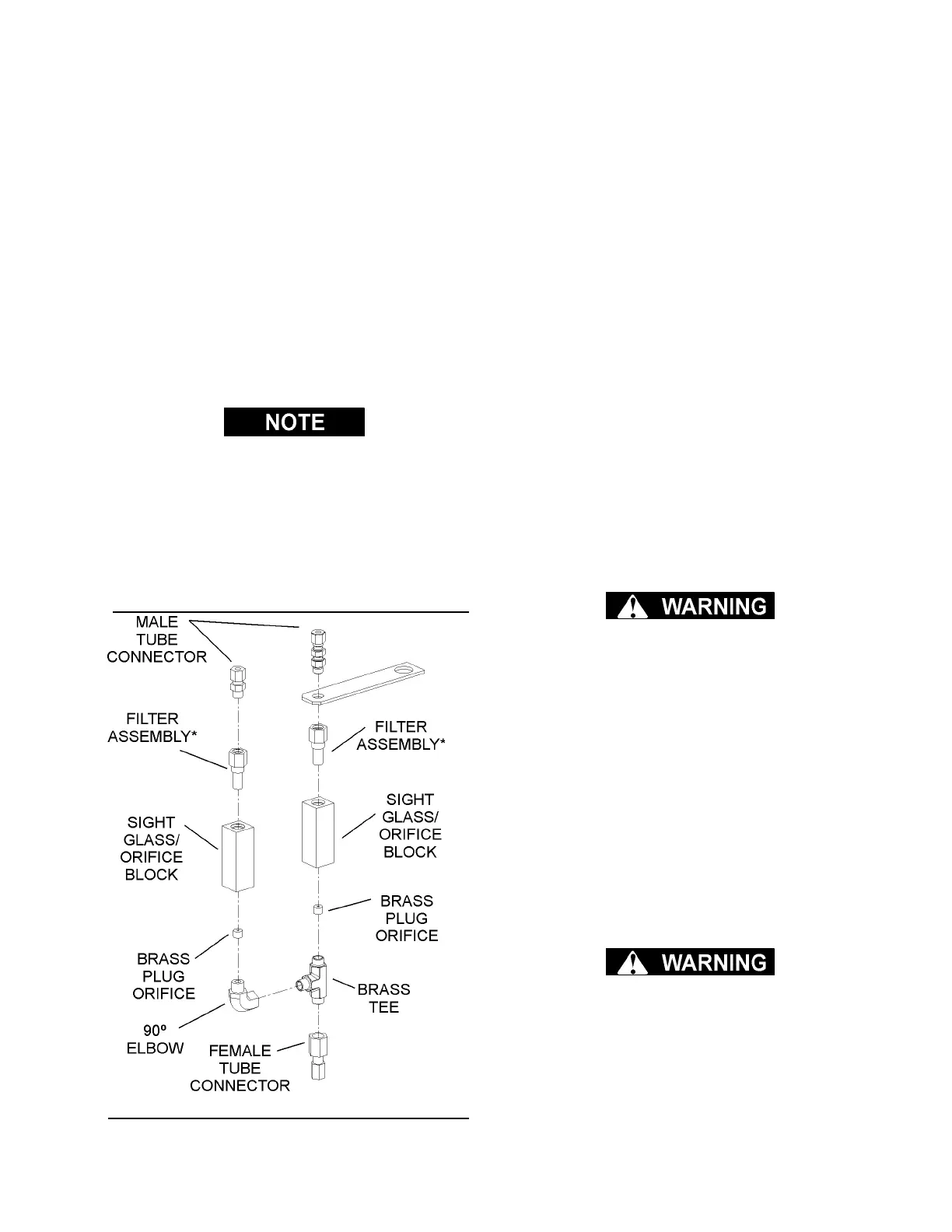
OIL RETURN/SIGHT GLASS MAINTENANCE
Refer to Figure 6-4. The oil return/sight glass sub-
assembly is attached to the separator tank lid. Oil
return/sight glass maintenance should be per-
formed on a routine basis parallel to that of the fluid
filter, or as indicated in the Troubleshooting
Sections (both Supervisor II and Maintenance) of
this manual. The maintenance on an oil
return/sight glass is mainly concerned with the con-
dition of the filter assembly. Order filter assembly
no. 02250117-782, and use the following instruc-
tions as a guide.
Always performing maintenance on both oil
return/sight glasses at the same time.
1. Disconnect the tubes at the tops of the sight
glass assemblies.
2. Unscrew male connector (for left-side glass), or
the straight thread tube connector (for right-side
glass) from sight glass/orifice blocks.
3. Remove used filter assembly, and replace with
new assembly.
4. Coat/lubricate the o-rings will silicone grease.
5. Reattach the connectors to the sight glass/orifice
blocks.
DIFFERENTIAL PRESSURE REGULATOR
ADJUSTMENT
Refer to Figure 6-5 and 6-6. The differential pres-
sure regulators are adjusted by loosening the
adjusting screw on the end of the cone-shaped
cover of the pressure regulator. When the jam nut
is loose, turn the adjusting screw clockwise to
increase or counterclockwise to decrease the set-
ting.
The reference pressure regulator should be set to
maintain a 60 psig (4.14 bar) downstream pressure
to the inlet poppet valve. The unload pressure reg-
ulator should be set at 175 psig (12.1 bar) to con-
trol the compressor package during unload only.
The inlet poppet valve control pressure regulator
should be set to control the systems modulation to
the service line desired pressure.
DRIVE COUPLING INSTALLATION AND ALIGN-
MENT
Applies to base-mounted compressors and drives
only. Units mounted through common housing
are self-aligning. If alignment is suspect, use the
following procedure.
Refer to Figures 6-6, 6-7 and 6-8. For coupling
installation and alignment, the tools required will be
one set of standard allen wrenches and a dial indi-
cator. If a dial indicator is not available, an alternate
method of checking the alignment may be used as
a secondary or less desirable technique. This
method of checking is done by careful use of a
square or metal straight edge feeler gauge and a
set of inside calipers (see Figure 6-8). Those spec-
ifications in Table 6-1 Installation Data which are
designated in inches are provided for this method.
For installation and maintenance of the drive cou-
pling, follow the steps explained below.
Disconnect all power at source, before attempting
maintenance or adjustments.
STEP 1 - MOUNT HUBS
After, carefully inspecting the hub bores and the
shafts for dirt and burrs, mount the motor hub and
the compressor hub on their respective shafts. It is
also necessary to check for a proper key fit. Place
Figure 6-4 Oil Return/Sight Glass
*Replacement Filter Assembly P/N 02250117-782
 Loading...