Section 2
DESCRIPTION
7
fluid flows to the main filter and on to the compres-
sor unit. The fluid filter has a replacement element
and an integral pressure bypass valve.
The fluid stop valve prevents fluid from filling the
compressor unit when the compressor is shut
down. When the compressor is operating, the fluid
stop valve is held open by air pressure from the
compressor unit allowing a free flow of fluid from
the receiver/sump back to the compressor unit. On
shutdown, the compressor unit pressure is
reduced, causing the fluid stop valve to close and
isolate the compressor unit from the cooling sys-
tem.
2.5 COMPRESSOR DISCHARGE SYSTEM, FUNC-
TIONAL DESCRIPTION
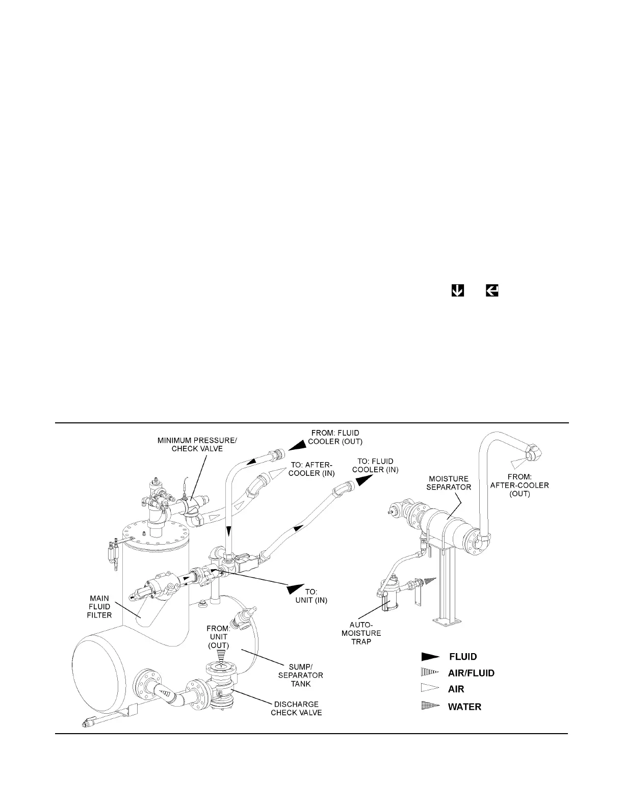
Refer to Figures 2-2, 2-3A and 2-3B. The compres-
sor unit discharges the compressed air/fluid mois-
ture through a discharge check valve into the com-
bination receiver/sump. The discharge check valve
prevents air in the receiver from returning to the
compression chamber after the compressor has
been shut down. The receiver has three functions:
• It acts as a primary fluid separator.
• Serves as the compressor fluid sump.
• Houses the final fluid separator elements.
The compressed air/fluid mixture enters the receiv-
er and is directed against the ends of the tank. The
direction of movement is changed and its velocity
significantly reduced, thus causing large droplets of
fluid to form and fall to the bottom of the
receiver/sump. The fractional percentage of fluid
remaining in the compressed air collects on the sur-
faces of the dual separator elements as the com-
pressed air flows through them. Two return lines (or
scavenge tubes) lead from the bottom of each sep-
arator element to the interstage of the compressor
unit. Fluid collecting on the bottom of each separa-
tor is returned to the compressor by a pressure dif-
ference between the receiver and the compressor.
Sight glasses are located in the return lines to
observe this fluid flow. There are also orifices in this
return line (protected by strainers) to assure proper
flow. By pressing the + pads on the
Supervisor Controller, the operator may monitor the
condition of the separator elements by reading dif-
ferential pressure on the digital display. At a differ-
ential of 10 psid (0.7 bar) or greater, the operator
will be told to service the separator element. At this
time, separator element replacement is necessary.
The receiver is an ASME pressure vessel. A combi-
nation minimum pressure/check valve, located
Figure 2-2 Compressor Cooling, Lubrication and Discharge System


 To Next Page