Do you have a question about the Sullair LS20 and is the answer not in the manual?
General guidelines for safe operation and maintenance of the compressor.
Requirements for operator PPE, including eye, face, and hearing protection.
Installation of flow-limiting valves for pressure release in air lines.
Precautions against fire and explosion due to lubricants, vapors, and ignition sources.
Instructions to keep body parts and clothing away from moving components.
Warnings regarding the use of compressed air for breathing and handling of fluids.
Safety procedures for electrical installation, maintenance, and avoiding shock.
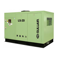
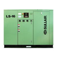
Overview of the main components and assemblies of the air compressor package.
Detailed functional description of the Sullair rotary screw compressor unit.
Functional description of the cooling and lubrication system for air-cooled models.
Functional description of the capacity control system using the Supervisor Controller.
Functional description of the capacity control system using electro-mechanical valves.
Description of the air inlet system, including air filter and inlet valve.
Description of the instrument panel gauges and controls for the electro-mechanical controller.
Detailed specifications including HP, capacity, dimensions, and weight for various models.
Guidelines for selecting and using compressor lubricants for optimal performance.
Recommendations for fluid and filter changes based on operating hours and conditions.
Requirements for compressor mounting, foundation, and leveling.
Ventilation requirements for air-cooled and water-cooled compressor installations.
Procedures for checking and maintaining the correct fluid level in the compressor.
Electrical preparation steps for electro-mechanical controlled compressors.
Procedure to check the motor rotation direction for standard electro-mechanical units.
Procedure to check the motor rotation direction for Supervisor controlled units.
Description of the keyboard keys and their functions on the Supervisor controller.
Explanation of the information shown on the Supervisor controller's main display.
Display of current operating status including pressures, temperatures, inputs, and outputs.
Parameters for controlling operation, including pressure, temperature, and timer settings.
Display of preventive maintenance schedules and timers for service.
Procedure for calibrating pressure readings using correction factors.
Procedure to verify correct motor rotation direction before starting.
Step-by-step guide for the first-time start-up of the compressor.
Introduction to troubleshooting procedures and general inspection advice.
Chart listing common messages, probable causes, and remedies for Supervisor controller.
Describes compressor behavior after power loss and restart conditions.
Explanation of the purpose and function of controls and indicators on the panel.
Step-by-step procedure for initial start-up of the electro-mechanical controller.
Introduction to troubleshooting for electro-mechanical systems and general inspection.
Guide for diagnosing and resolving common issues with electro-mechanical controllers.
Routine checks to perform before starting the compressor daily.
Procedures for draining and changing compressor fluid.
Guidelines for replacing fluid filter elements and gaskets.
Procedure for replacing separator elements as indicated.
Detailed procedures for replacing common parts and making adjustments.
Overview of components specific to variable speed drive (VSD) applications.
Functional description of the control system for VSD compressors with Supervisor Controller.
Procedure for setting up the Supervisor Controller and Variable Speed Drive.
Instructions on how to order replacement parts from Sullair.
List of recommended spare parts for routine maintenance and repairs.
Illustration and parts list for the motor, compressor, and frame assembly.
Illustration and parts list for the air inlet system of air-cooled models.
Illustration and parts list for the air inlet system of water-cooled models.
Illustration and parts list for the fluid piping system of air-cooled models.
Illustration and parts list for the sump and associated components.
Illustration and parts list for pneumatic controls used with Supervisor Controller.
Illustration and parts list for pneumatic controls used with Electro-Mechanical Controller.
Illustration and parts list for the control box of Supervisor Controller units.
Illustration and parts list for the control box of Electro-Mechanical units.
Wiring diagram for LS20-100HP with full voltage Supervisor Controller.
Wiring diagram for LS20-100HP with full voltage Electro-Mechanical Controller.
| Brand | Sullair |
|---|---|
| Model | LS20 |
| Category | Air Compressor |
| Language | English |