Section 11
VARIABLE SPEED DRIVE APPLICATIONS
57
11.1 DESCRIPTION OF COMPONENTS
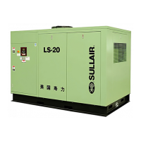
Refer to Figures 11-1A, 11-1B and 11-2. The com-
ponents and assemblies of the air compressor are
clearly shown. The complete package includes
compressor, electric motor, control center,
variable speed drive controller, compressor
inlet system, compressor discharge system,
compressor lubrication and cooling system,
capacity control system, instrument panel,
aftercooler, and combination separator and trap,
all mounted on a heavy gauge steel frame.
On air-cooled models, a fan draws air over the
motor and forces it out through the combined after-
cooler and fluid cooler thereby removing the com-
pression heat from the compressed air and the
cooling fluid.
On water-cooled models, a shell and tube heat
exchanger is mounted on the compressor frame.
Fluid is piped into the heat exchanger where com-
pression heat is removed from the fluid. Another
similar heat exchanger cools the compressed air.
Both air-cooled and water-cooled versions have
easily accessible items such as the fluid filters and
control valves. The inlet air filter is also easily
accessible for servicing.
11.2 CONTROL SYSTEM, FUNCTIONAL DESCRIP-
TION SUPERVISOR CONTROLLER
Refer to Figure 11-2. The purpose of the compres-
sor control system is to regulate the amount of the
air being compressed to match the amount of com-
pressed air being used. The capacity control sys-
tem consist of variable speed drive, solenoid valve,
regulating valve, and the inlet valve. The functional
description of the control system is described below
in five distinct phases of operation. The following
description text applies to LS20 series variable
speed drive compressors with Supervisor
Controller. For explanatory purposes, this descrip-
Figure 11-1A Sullair Rotary Screw Air Compressor- 100HP Air-cooled with Variable Speed
(typical component layout)
(I) DO NOT Operate compressor without cooler access panels in place (see Figure 2-1B in Section 2, Description).