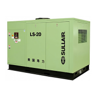
Section 2
DESCRIPTION
14
plant piping.” (I)
Sullube should not be used with PVC piping sys-
tems. It may affect the bond at cemented joints.
Certain other plastic materials may also be affect-
ed.
(I) Plastic Pipe Institute, Recommendation B,
Adopted January 19, 1972.
2.9 INSTRUMENT PANEL GROUP, FUNCTIONAL DE-
SCRIPTION- ELECTRO-MECHANICAL CON-
TROLLER
Refer to Figure 2-7 for specific location of parts
described. For information on Supervisor Controller
panel group, see Section 5, Supervisor Controller.
The Electro-mechanical Controller Instrument
Panel Group consists of a panel containing the line
pressure, sump pressure and discharge tempera-
ture gauges, the air filter, the separator element and
the fluid filter, restriction gauges, along with START
and STOP push buttons and an hourmeter.
Refer to Figure 2-7 for locations of the following
indicators and controls:
• The line (terminal) pressure gauge is connected
to the dry side of the receiver downstream from the
check valve and continually monitors the air pres-
sure.
• The sump pressure gauge continually monitors
the sump pressure at the various load and/or
unload conditions.
• The discharge temperature gauge monitors the
temperature of the air leaving the compressor unit.
For both air-cooled and water-cooled compressors
the normal reading is approximately 180°F to 205°F
(82°C to 96°C).
• The air filter restriction gauge monitors the con-
dition of the air intake filter and shows in the red
zone (20 to 30” water [51 to 76 cm]) when filter
service is required. The compressor must be run-
ning fully loaded for an accurate indication.
• The START (I) pad turns the compressor on.
• The STOP (O) pad turns the compressor off.
• The hourmeter records accumulative hours of
operation for the compressor and is useful for plan-
ning and logging service operations.
• The POWER ON ( ) LED on the instrument
panel indicates when power to the compressor is
supplied.
• The ON LED indicates when the compressor is
running.
• The AUTO ( ) pad is used to enable automat-
ic control.
• The separator maintenance gauge monitors
condition of the separator element and shows in the
red zone when the element restriction is excessive.
• The fluid filter maintenance gauge monitors the
condition of the bearing lube filter element and
shows in the red zone when the element should be
changed.
Figure 2-7 Instrument Panel Group