Section 2
SUPERVISOR II SEQUENCING
14
If the up arrow key is pushed the system line pressure is displayed. If the up arrow key is
pushed again the line pressure and run hours of the first machine is displayed, if the arrow
key is pushed again the second machine is displayed and so on. The lamp test key changes
to the previous display.
REMOVING A MACHINE FROM SEQUENCE FOR MAINTENANCE
Make sure that ROTATE HOURS is disabled for all machines.
To temporarily disable a machine from sequencing for maintenance, simply press the STOP
pad then depress the E-Stop Button, remove power to that machine and apply the appro-
priate Lockout/Tagout procedure. The rest of the networked machines will continue to
sequence properly. When restoring the machine to the network, simply restore power, pull
out the E-Stop, press STOP and then AUTO. If the sequencing parameters have not been
changed, the machine will sequence in at the appropriate time. By revising that machine's
SEQUENCE HOURS before enabling sequencing, one may force it to move up or down in
the start priority in the HOURS sequencing mode.
To permanently remove a machine from sequence, reprogram the other compressors as
though the downed machine/s is/are not there. (Relocate the COM NUMBERS as needed
and change the LAST COM value per the number of machines removed.) Remember that
any program changes must be done while the machine is manually stopped.
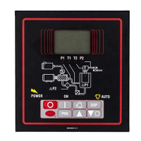
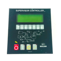
CALIBRATION OF P2 PRESSURE TRANSDUCERS
Because each machine has it's own pressure transducer it is possible that after a long peri-
od of time these can read differently. If this happens the supervisors should be re-calibrat-
ed.
This re-calibration is best done when the system is at a stable pressure. Measure the pres-
sure using an independent gauge then change the calibration parameter for P2 so that the
supervisor reads the same as the gauge.
The changing of the calibration parameters is entered by a special key sequence to protect
from inadvertent change. The key sequence is :
LOGO, UP ARROW, DISPLAY; LAMP TEST, PROGRAM
The first line of the display should read CAL P1 , if not push the display key and try again.
If the first line of the display reads CAL P1 push the program key, and the first line of the
display should read CAL P2. The second line of the display will show the calibration param-
eter ( + 7 to -7) and the current P2 reading corrected by the calibration parameter. The up
arrow key will increase the reading and the lamp test will decrease the reading. Use these
keys to correct the P2 reading, then push the program key. The program key must be
pressed after setting the calibration parameter to make it permanent. Return to the main
display and check to make sure the pressure is correct.
NETWORK WIRING
The network cable should be Belden 9842 or similar. This cable has two twisted pairs with
a shield. One twisted pair is connected to J2-16 and J2-17. Twisted pairs usually have one
colored wire twisted with a black or white wire. Make sure that the colored wire is on J2-16
 Loading...