Section 5
MAINTENANCE AND TROUBLESHOOTING
21
5.1 MAINTENANCE INTRODUCTION
Asyouproceed inreading this section, itwill beeasy
to see that Maintenance Program for the air com-
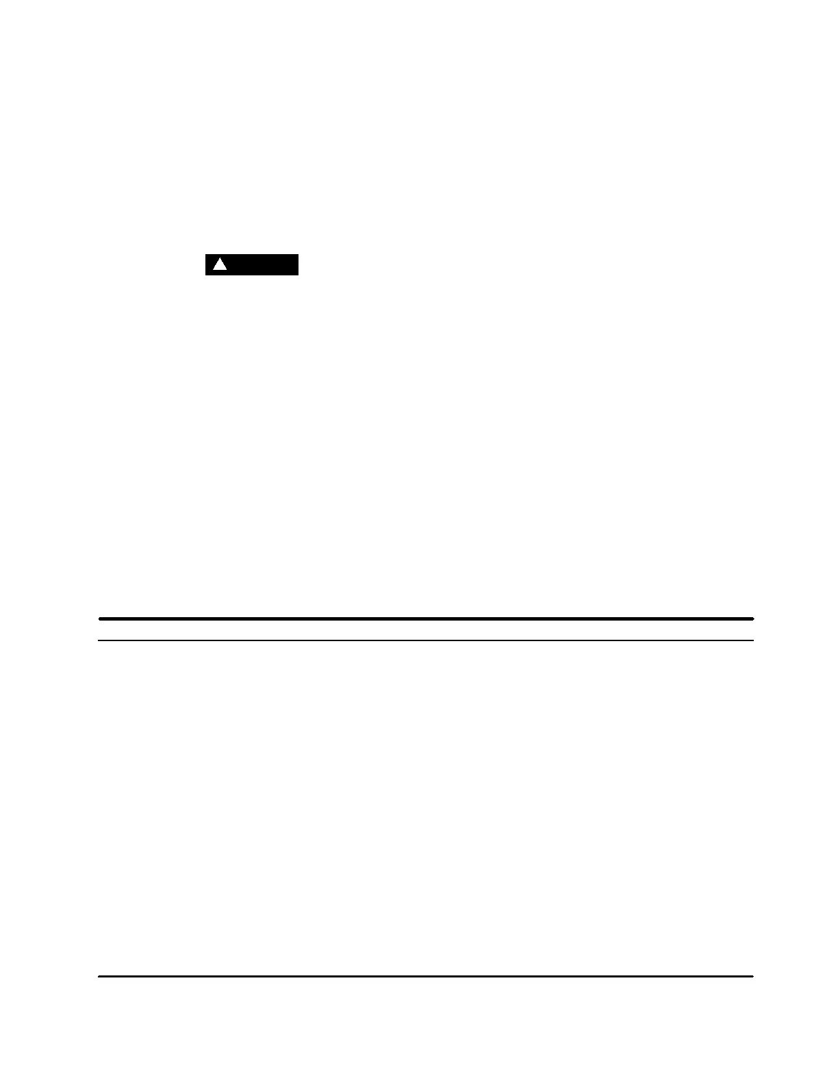
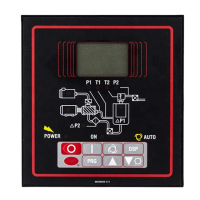
pressor is quite minimal. The Supervisor monitors
the status of the air filter, fluid filter, and separator
elements. When maintenance tothese devices isre-
quired, the Supervisor will display the appropriate
maintenance message and flash the location LED
on the graphics map as a visual reminder.
WARNING
!
DO NOT removecaps, plugs, and/or othercompo-
nents when compressor is running or pressur-
ized.
Stop compressor and relieveall internalpressure
before doing so.
5.2 DAILY OPERATION
F ollowingaroutine start, observe the variousSuper-
visor displays to check that normal readings are be-
ing made --- previous records are very helpful inde-
termining the normalcy of the measurements.
These observations should be made during all ex-
pected modes of operation (i.e. full load, no---load,
different line pressures, cooling water tempera-
tures, etc.).
During the initial start---up or servicing of the pack-
age, fluid may have tobe added to the sump vessel
to restore an adequate level. Frequent fluid addi-
tions to maintain said levelwould beindicative ofex-
cessive fluid consumption, and should be investi-
gated --- see the Troubleshooting Section of this
manual for probable cause and remedy.
5.3 TROUBLESHOOTING INTRODUCTION
The following information has been compiled from
operational experience with your package. It identi-
fies symptoms and diagnosis of SEVERAL probable
difficulties, but NOT ALL of those possible.
The systematic collection of operational data can-
notbe over---emphasized, as itmaygive evidence of
the presence (or not) of a fault before it turns into a
serious breakdown --- for example, the vibrations
signature increase ofadamaged bearing, ortheeffi-
ciency decrease of a dirty heat exchanger.
A detailed visual inspection is worth performing for
almost all problems and may avoid unnecessary
additional damage to the compressor. Always re-
member to:
1. Check for loose wiring.
2. Check for damaged piping.
3. Check for parts damaged by heat or an electrical
short circuit, usually apparent bydiscoloration or
a burnt odor.
Should your problem persist after making the rec-
ommended check, consult your nearest Sullair rep-
resentative or the Sullair Corporation.
5.4 TROUBLESHOOTING GUIDE --- SEE 5.4A THROUGH 5.4D FOR SPECIFIC MODELS
5.4 A --- ES --- 8 TROU BLESHOOTIN G GUIDE
SYMPTOM PROBABLE CAUSE REMEDY
T1 HI Message Discharge Temperature Exceeded
225˚ F (107 ˚ C) for Pre ---Alarm
Discharge Temperature Exceeded
235˚ F (113˚C) for Shutdown
Ambient Temperature Exceeded Improve local ventilation (i.e.,
105˚ F(41˚ C) remote intake of process and/or
cooling air.
Fluid Level in Sump is Too Low Check/correct fluid level.
Thermal Valve Malfunctioned Check/replace thermal valve.
Cooler Fins are Dirty Clean cooler fins.
Water Flow is Low (water---cooled Check cooling water supply (i.e.,
packages only) closed valves).
Water Temperature is High (water--- Increase water flow, lower water
cooled packages only) temperature.
Cooler is Plugged (water---cooled Clean tubes and/or shell --- if tube
packages only) p lugging persists, provide cleaner
water.
Temperature RTD Malfunction Check connections from RTD.
If adequate, replace RTD.