14
Beier frame size
Horizontal type
A type B type
N10A N8B
15A 10B
20A 15B
30A
40A
20B
30B
Trochoid pump Pump motor
Vertical type
Trochoid pump Pump motor
– – TOP-13AK 0.2kW 4P
– – TOP-208HB 0.4kW 4P
– – TOP-212HB 0.4kW 4P
– – TOP-216HB 0.75kW 4P
50A
75A
100A
150A
200A
50B
75B
100B
150B
TOP-212HB
TOP-N350HVB-7
With relief valve
0.75kW 4P TOP-N330H
TOP-N350HVB-7
With relief valve
2.2kW 6P
2.2kW 6P
Table 6 Trochoid Pump Specification for Beier portion
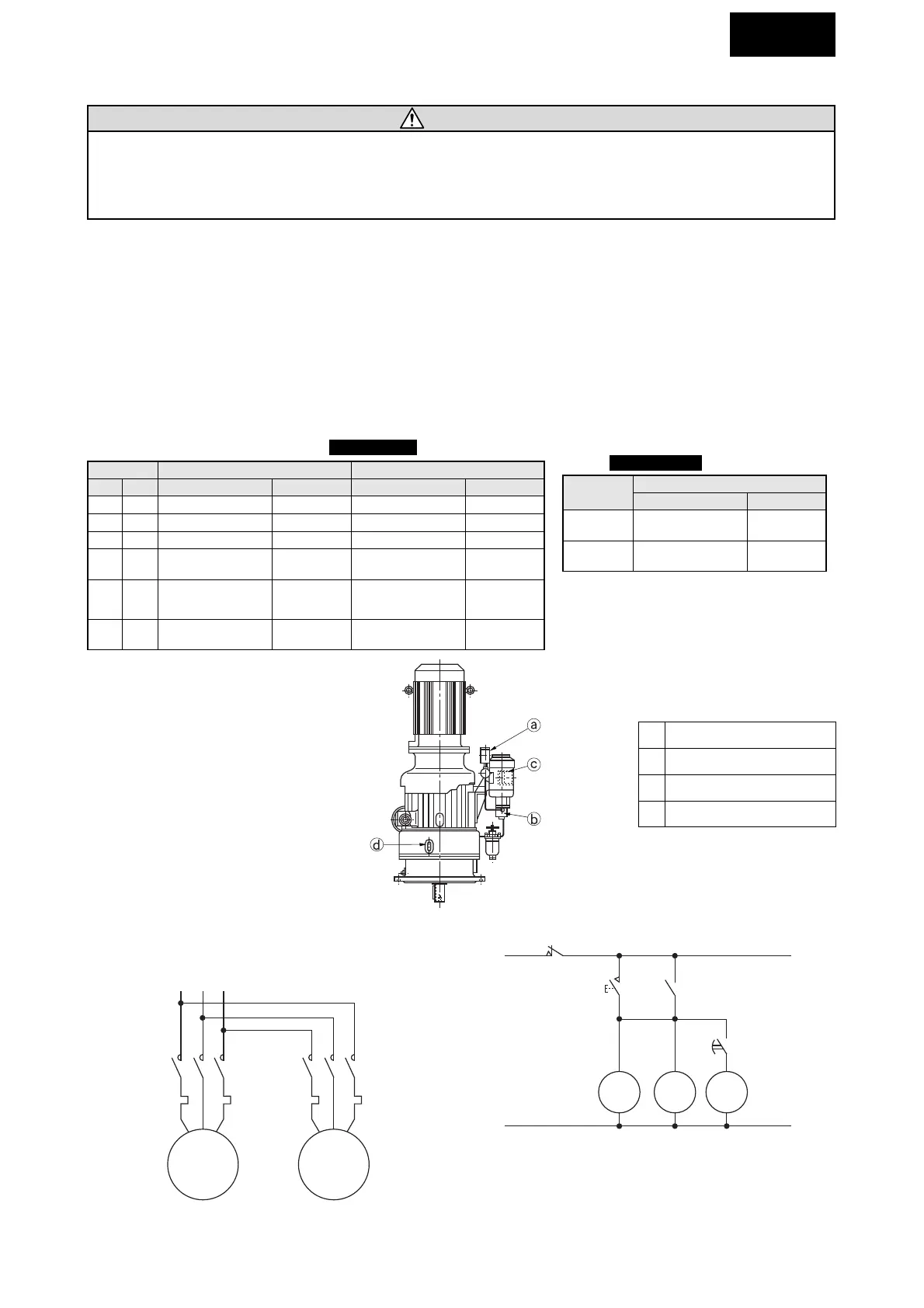
a
b
c
d
Pressure gauge
Trochoid pump
Motor (For Trochoid pump)
Oil level gauge
Fig. 10 Trochoid Pump Construction
Fig. 11 Torochoid Pump Wiring Diagram
MC1 : Electromagnetic switch (For Main motor)
MC2 : Electromagnetic switch (For Trochoid pump motor
PB1 : Push button switch (For Starting)
PB2 : Push button switch (For Stopping)
T : Timer (Approx, 30 sec. or more)
Cyclo frame
size
6275
Vertical type
Trochoid pump
TOP-216HBVB-3
With relief valve
Pump motor
0.75kW 4P
6275DA
TOP-204HBVB-3
With relief valve
0.4kW 4P
Table 7 Trochoid Pump Specification for
Cyclo portion
Lubrication oil cooling device will be
set separately for over 50A and 50B.
Refer to "9. Lubricating Oil Cooling
Device (page 28)."
COMMON
CAUTION
Conduct priming shown in the maintenance manual, before the start up of the main motor, in case of forced oil
lubrication by the trochoid pump; otherwise damage to the equipment may result.
For forced oil lubrication by trochoid pump, prime the pump, as shown in the maintenance manual, before starting
the main motor; otherwise, the equipment may be damaged.
(1) Because forced lubrication by the trochoid pump is necessary for the models with trochoid pump system as in "8-2
Confirmation of Lubrication Method (page 17)", a separate power source should be prepared for the pump. (Refer to
Table 6, 7 and Fig.10)
(2) Refer to Fig.11 for the trochoid pump wiring. At this point, connect so that the pump motor will rotate the designated
direction.
(3) Establish an electrical interlocking device between the trochoid pump motor and main motor that satisfies the following
two functions; (Refer to Fig.11)
1 Start-up time-The main motor stops when the trochoid pump stops.
2 During operation-The main motor stops when the trochoid pump stops for some unknown reason.
(4) To assure optimal lubrication conditions, the trochoid pump should be started-up at least 30 seconds before the start-up
of the main motor. (priming)
6-6) Trochoid Pump Connection

 Loading...


