31
OP
11. Remote Control Equipment
(OPTION)
11-1) Speed Control Device
(2) Handling of the Pilot Motor (PM)
Both worm gear-type and Cyclo Drive-type pilot motors are available to match the different Beier types.
· Never conduct operations while the Beier Variator is stopped.
(1) Checking Wiring and Speed Control Operation
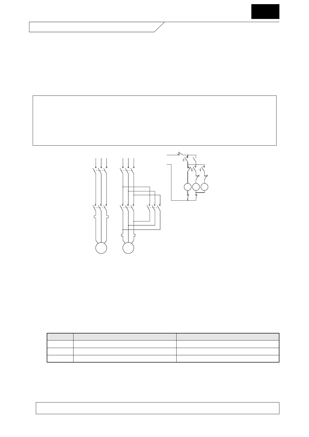
· An example of control circuit for pilot motor and push button is shown in Fig. 23 . To check the connection, start the
main motor first. Then, confirm that the revolution speed of output shaft increases while depressing the speed
increase button (PB4). Also confirm that the revolution speed of output shaft decreases while depressing the speed
decrease button (PB3). If the operation is reversed, interchange two phases of power supply to the pilot motor (PM).
· When highest speed or lowest speed has been reached, check to confirm slip clutch is idling, thereby positively
protecting both PM and speed change control device.
· Handling of the worm gear-type pilot motor (PM)
This pilot motor is a maintenance-free motor, which incorporates a ball clutch as a safety device.
To remove the pilot motor from the Beier main body, pull out the PM mounting bolts (3 bolts ) first.
Then pull out the whole PM from the operating shaft. If it becomes necessary to change the manual speed, shut off the power
of the pilot motor, and use a hexagon bar wrench (nominal 5) to turn part A.
Fig. 23 Connection Diagram
NFB : Auto Breaker
MC1 : Electromagnetic Switch (Main Motor)
MC2D : Electromagnetic Switch (PM, Speed Decrease Side)
MC2U : Electromagnetic Switch (PM, Speed Increase Side)
PB1 : Start Button
PB2 : Stop Button
PB3 : Speed Decrease Button
PB4 : Speed Increase Button
PB5 : Emergency Stop Button
M : Main Motor
PM : Pilot Motor
THR : Thermal Protection Relay
Table 42 Beier Type and Pilot Motor Type
Worm gear motor type Cyclo Drive type
A Type N02A, N05A, N1A, N2A, N3A, N5A, N8A, N10A 15A, 20A, 30A, 40A, 50A, 75A, 100A, 150A, 200A
B Type N02B, N05B, N1B, N2B, N3B, N5B, N8B 10B, 15B, 20B, 30B, 50B, 75B, 100B, 150B
D Type N05D, N1D, N2D, N3D, N5D, N8D, N10D
• There is a possibility of speed control failure if clutch is left slipping for 30 seconds or more while speed control
operation is sustained at maximum or minimum speed. Do not fail to stop PM as soon as possible by releasing
pushbutton for control. To prevent such problem, check change in rotation speed using electromagnetic tachometer
while conducting speed control operation.
• For cases when clutch stays slipping because of the content of speed control, optional limit switch system is
recommended.
• When stopping Beier Variator, never turn speed control handwheel. For Beier with remote control, connect power
source of speed control pilot motor from the secondary side of power source of main motor.

 Loading...


