33
OP
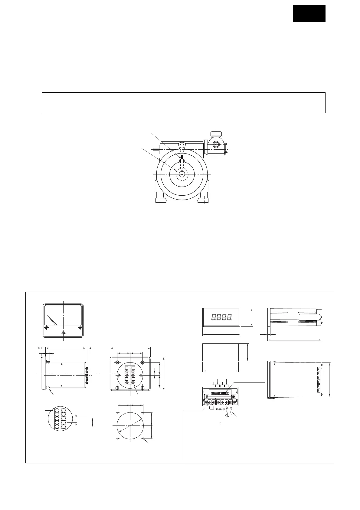
11-2) Speed indicators
(2) Connect the auxiliary power source to the two tachometer terminals.
Auxiliary power specification
Analog tachometer : Common for AC100V 50/60Hz, AC200V 50/60Hz
Digital tachomenter : AC100V 50/60Hz
This tachometer has graduated output revolutions.
(3) For use of explosion proof type, refer to the Speed Setter SP-20E catalog.
• Use a twisted shield wire measuring 0.5mm
2
or more for the wiring. Separate the shield wire from the power line. The
connection distance must be no more than 100m.
Electromagnetic tachometer (for non explosion proof type).
(1) Connect the lead wire of the Beier Variator electromagnetic sensor to the two tachometer terminals. When shield
wire is used with digital tachometer, shield can be connected to the (–) side of sensor input. For analog tachometer,
connection of shield is not necessary. (Assess whether or not to connect the shield wire since the noise intensity may
become greater if unconnected.)

 Loading...


