8
FB BRAKE ASSEMBLY – INSPECTION,
ADJUSTMENT & MAINTENANCE
SM-Cyclo FB series brakemotors are designed to be
mechanically rugged, electrically reliable and efficient
in operation. To maintain this reliable performance,
the brake assembly must be inspected and adjusted
periodically.
Brake Models FB-01A, FB-02A and FB-05A
1. Standard Brakemotor Specifications
Table 8 lists the standard specifications for Models
FB-01A, FB-02A and FB-05A.
This section of the manual pertains specifically to the
brake portion of the SM-Hyponic gearmotor and
provides all the necessary information to insure long
and trouble-free service.
Table 8 Models FB-01A, FB-02A, FB-05A Standard Specifications
Brake Motor
Brake Inertia
Brake
Brake Current
Coil
Brake Delay Time
Type HP
Torque WK
2
Coil
(A)
Resis
(seconds)
ft-lb lb-ft
2
230V 460V
ohms
Normal Fast
FB-01A 1/8 0.7 0.0083
DC Energized
0.1 0.06 2700 0.15 ~ 0.2 0.015 ~ 0.02
FB-02A
1/4
1.4 0.0131
Type, Built-in
0.1 0.06 1791 0.15 ~ 0.2 0.015 ~ 0.02
1/3
Rectifier within
FB-05A 1/2 2.9 0.016
Conduit Box
0.1 0.06 1791 0.1 ~ 0.15 0.01 ~ 0.015
Notes:1) Continuous time rating for both the brake and motor.
2) Indoor types can be installed for use in any orientation.
2. Construction and Operating Principles
a. Construction
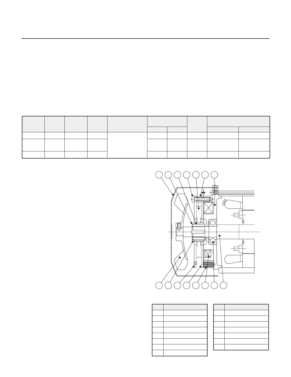
Fig. 17 illustrates the construction of the brake.
The restraining bolt (4) fastens the brake shoe (10)
and spacer (2) onto the stationary core (1). The
armature plate (11) is kept from rotation by the
restraining bolt (4) but moves axially by
electromagnetic attraction and the tension of the
pressure spring (12). The brake lining (3) is fitted
to the hub (5), which is secured to the motor shaft
with a key. The solenoid coil (13) is energized via
a rectifier located within the conduit box.
b. Operating Principles
The brake is a (fail-safe type) spring actuated type
brake that releases the brake mechanism when the
solenoid coil is energized and engages when the
solenoid coil is not energized.
When power is applied to the unit, the solenoid coil
and electric motor become energized and the
energized coil attracts the armature plate (11)
against the tension of the pressure spring (12). As
a result, the brake lining (3) disengages and the
motor starts to run.
When the power is disconnected, the solenoid coil
and electric motor are not energized. This causes
the pressure spring (12) to actuate the armature
plate (11), which in turn presses the brake lining (3)
against the brakeshoe (10) and brings the motor to
a quick stop.
No. Part Name
1 Stationary Core*
2 Spacer*
3 Brake Lining*
4 Restraining Bolt*
5 Hub*
6 C-type Retaining Ring
7 Cover
8 Fan (TEFC model only)
No. Part Name
9 Leaf Spring*
10 Brake Shoe*
11 Armature*
12 Pressure Spring*
13 Solenoid Coil*
14 Ball Bearing
15 Motor Shaft
*These parts are included in a complete brake kit.