1
MOUNTING
Solid Shaft Type
1. Mounting conditions
Ambient temperature: 14°F ~ 104°F
Humidity: 85% or less
Altitude: Lower than 3300 ft (1000 m)
above sea level
Atmosphere: Free from corrosive gases,
explosive gases or steam. It
should also be free from dust
and well ventilated.
Location: Indoors
2. Mount the gearmotor on a rigid surface.
3. There is no restriction for mounting angle.
4. Use hexagon socket head bolts when mounting
RNFM series (flange-mount type). See Table 1 for
bolt sizes.
Table 1
Series Frame Size Size of hexagon socket head bolt
20˝, 23˝ M8
30˝, 33˝ M10
RNFM
40˝, 43˝ M10
50˝, 53˝, 54˝ M12
Hollow Shaft Type
1. Mounting conditions
Ambient temperature: 14°F ~ 104°F
Humidity: 85% or less
Altitude: Less than 3300 ft (1000 m)
above sea level
Atmosphere: Free from corrosive gases,
explosive gases, steam and
dust. It should also be well
ventilated.
Location: Indoors
2. Mount the gearmotor on a driven shaft that has
sufficient rigidity.
3. There is no restriction for the mounting angle.
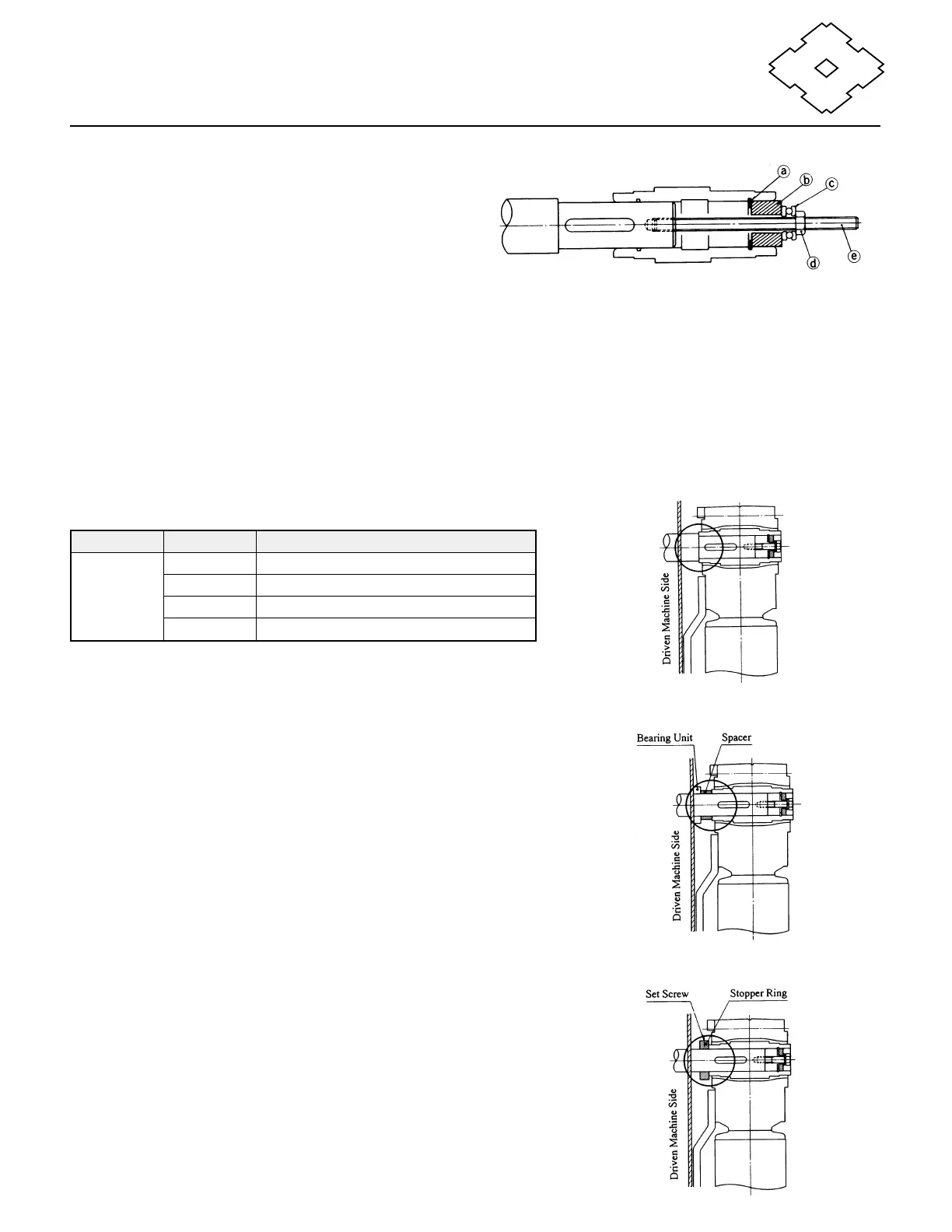
4. Mounting Procedures
a. Connecting a Driven Shaft
Apply molybdenum disulfide grease to the surface
of the shaft and the inner surface of the hollow
shaft. Slide the SM-Hyponic onto the shaft. To
make the installation smoother if the fit is too tight,
lightly tap the end of the hollow output shaft with a
wooden hammer. Avoid hitting the casing. To
ensure smooth installation of the drive, we
recommend the use of a jig shown in Fig. 1.
The hollow shaft is made according to ISO H8
tolerances. Following installation, ensure that the
fitting between the hollow and the driven shaft is
tightened correctly. We recommend ISO js6 or k6
as the tolerance for the driven shaft.
b. Mounting the SM-Hyponic gearmotor
Fig. 1
a – Retaining ring d – Nut
b – Spacer e – Double-ended threaded bolt
c – Thrust bearing
Fig. 2 Stepped Shaft Option
Fig. 3 Spacer Option
Fig. 4 Set Screw Option