3
MOUNTING
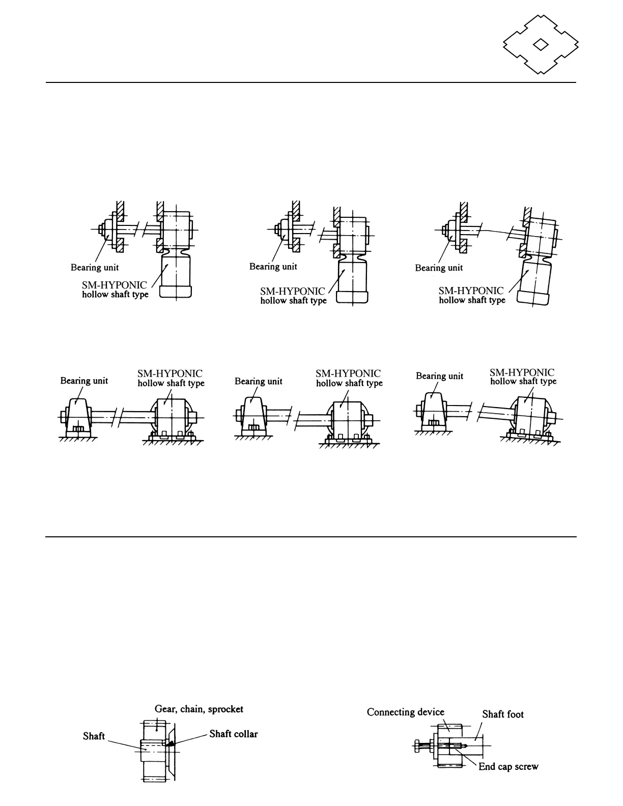
(5) Flange and Foot Mounting (optional).
When installing the SM-Hyponic, ensure that the
gearmotor and the shaft of the driven machine are
properly aligned so that the drive is free from
excessive force.
Good example Bad example Bad example
Fig. 10 Flange coupling
(The concentricity between the
shaft and mounting pilot is out of
allowable range.)
(The shaft centerline is not
positioned at right angles to the
flange.)
Good example Bad example Bad example
Fig. 11 Foot mounting
(optional)
(The shaft center of the bear-
ing unit does not align with
that of the Drive.)
(The parallelism of the
mounting beds is out of
allowable range.)
CONNECTING TO THE DRIVEN MACHINE
Solid-shaft type
1. Mount the connecting device, such as a coupling,
chain, sprocket, gear or V-pulley, on the shaft as
close as possible to the shaft collar. This places
the load point between the center of the shaft and
the shaft collar.
2. We recommend using end cap screws to avoid
possible bearing damage from excessive force or
thrust load that may be applied to the shaft while
fitting the connecting device.
3. When connecting the SM-Hyponic gearmotor to the
driven machine, be sure to align the shafts of both
units (for coupling connection) or keep both shafts
parallel (for chain, gear or V-belt connection).
4. Excessively loose chains will cause a jolt upon start-
up that may damage the SM-Hyponic gearmotor and
the driven machine. Excessive tension of V-belts
may cause bearing failure.
Fig. 12
Fig. 13