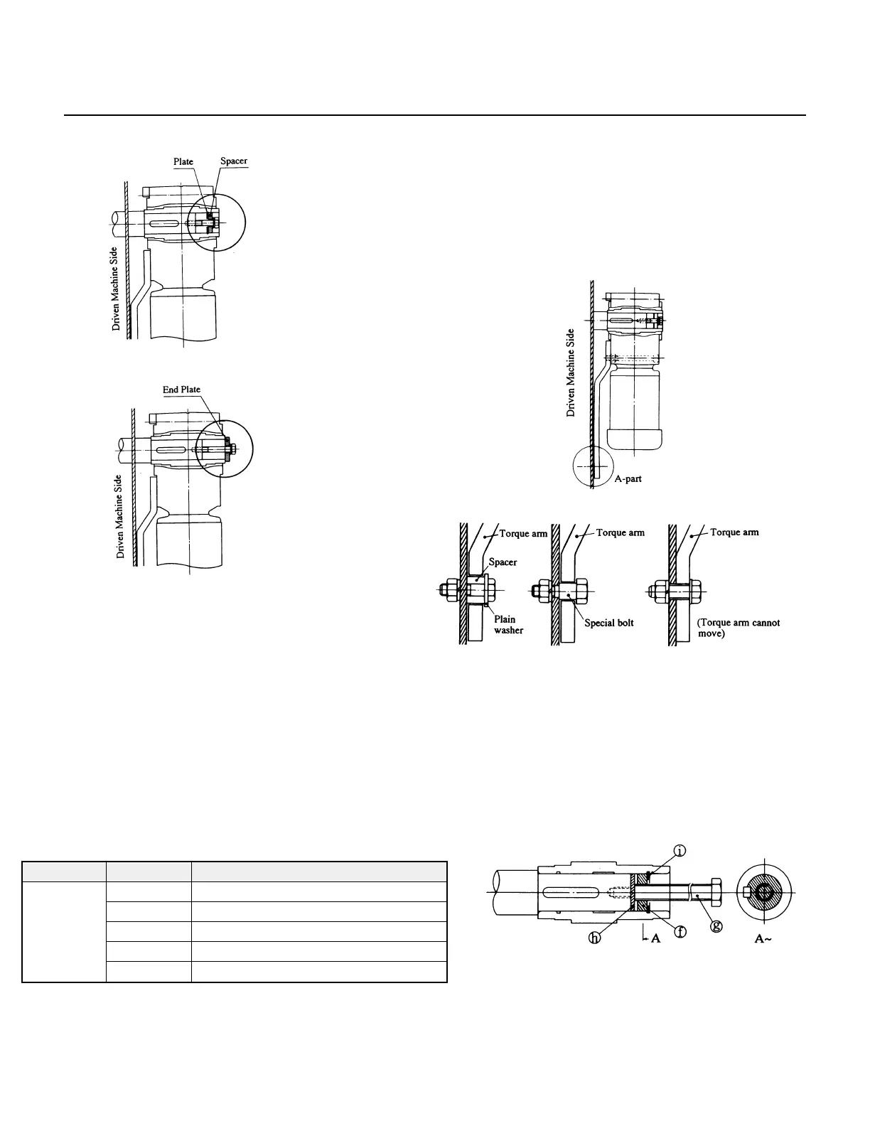
Fig. 5 Spacer and Plate Option
Fig. 6 End Plate Option
(c) Installing the torque arm.
Mount the torque arm on the driven machine side of
the drive casing. Use hexagon socket head bolts for
mounting. (See Table 2 for bolt sizes.)
Table 2
The torque arm (Section A in Fig. 8) should be mounted
to ensure that the contact surface between the drive and
shaft are free from excessive forces. Do not attach the
torque arm using anti-rotation bolts.
For applications that require frequent starts and stops or
frequent reversing, insert a rubber bushing between the
torque arm and securing bolt (or spacer) in order to
dampen impact load.
Fig. 8 Torque Arm Securing Methods
(d) Removing the shaft.
Do not apply excessive force to the gearmotor and shaft.
Using a jig as shown in Fig. 9 will facilitate removal of
the shaft.
Note: The customer should prepare parts for setting, securing or removing
the shaft.
Fig. 9
Series Frame Size Size of hexagon socket head bolt
20, 23 M8
30, 33 M10
RNFM 40˝, 43˝ M10
50˝, 53˝, 54˝ M12
60, 63, 64 M20
f – Spacer g – Bolt
h – Plate i – Shaft retaining C-ring
WARNING: Inappropriate installation may r
esult in shaft fretting.
Fretting will cause shaft wear, jamming, and misalignment between
the drive and Customer's
shaft.