- 9 -
- 20 -
Symptom Cause Remedial Action Prevention
Urine Odor
Around
Unit
Horizontal runs or
downward slopes
on pipe are causing
condensate to
block pipe.
Fan has failed (110
volt) (Electric and
AC/DC)
Fan has failed (12
volt) (AC/DC and
NE)
Device other than
Sun-Mar diffuser is
installed on top of
the vent stack
Room where unit is
located is airtight.
2” Vent stack has
too many bends
and/or horizontal
lengths. (Electric
and AC/DC)
Install wall brackets on vent pipe to
prevent settling. DO NOT install hori-
zontal runs as liquid will collect and
block ventilation, causing odor.
The fan is a constantly moving part
and has a finite service life.
The fan is a constantly moving part
and has a finite service life.
Wind turbines or vent caps
should not be installed on or, instead
of a Sun-Mar diffuser.
Install your CENTREX 2000 in an
area with plenty of ventilation and
watch for competing appliances such
as bathroom fans and wood stoves.
Install the vent with minimal bends
(total bends should equal no more
than 360 degrees) and NO horizon-
tal or downward slopes.
Installation
Considerat-
ions for the
waste pipe
The 3” Waste
Inlet
Drain
Installation
When installing the waste piping from the toilet to the composting unit, the following considerations
should be born in mind:-
i) The piping should be either 45 degrees or more to the vertical (if composting unit is directly below
toilet), or at a 2-3 degree angle (1/8”-1/4” or 3-13mm drop per foot maximum) so that the waste
travels with the liquid.
ii) Piping should not slope upwards at any point.
iii) Connections should be snug so that waste is not encouraged to “hang up” where pipe meets
connector.
iv) It is recommended that the waste pipe not be longer than 15 feet (460cm) without installing a clear
out port(a Y fitting with screw on end cap) near the toilet to provide easy access should it ever be
required.
v) Use a soft sealant, such as silicone for the connection of the waste piping to the composting unit so
that the composting unit can be moved for servicing or other reasons should this ever be required.
vi) Insulate piping if unit is to be used during the winter.
For heavy winter use, the composting unit will need to be kept warm by enclosing it, insulating the
enclosure, and providing some heat source. The enclosure must not be airtight since the unit
must be able to draw air in.
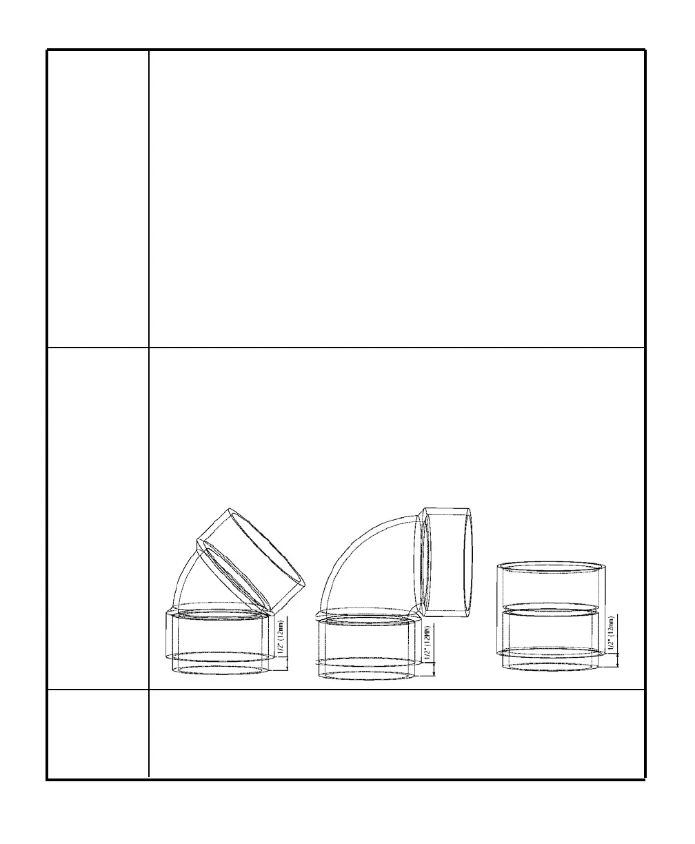
The 3”(75mm) waste inlet (supplied with kit) should be installed where the waste pipe feeds into the
composting unit. This assembly will allow the waste to flow into the Bio-Drum without interfering with the
drums’ function. If more room is needed in your installation, you can substitute this assembly by con-
structing your own 3” (75mm) waste assembly from the examples shown below.
This assembly can be constructed by using a 3 (75mm)inch coupling or elbow (as shown below) and a
piece of 3 inch(75mm) pipe. Glue the pipe into the end of the coupling or elbow that will sit on the
composting unit waste inlet opening. Cut this pipe so that only 1/2”(13mm) protrudes from the coupling
or elbow. This pipe will fit in the waste inlet hole and should end just above the opening in the drum,
without interfering with drum movement.
The drains must be connected for all applications. The 1” (25mm)Safety drains at the left of the
“Centrex 2000”, exit to both the front and back. To connect one of the drains, (whichever is conven-
ient), remove the plug, attach the 1”(25mm) hose (included) and secure with a hose clamp. Ensure
there are no kinks or upward bends in the drain hose.
Re-install the vent so there are no longer any low
points where condensate can collect. If re-instal-
lation is not possible, drill a small hole in the bot-
tom of the low point (preferable outdoors) to
allow condensate to drain. (Note: watch for icing
in winter at this hole.)
Have your serial number ready and call Sun-Mar
for a replacement. Instructions are included with
the replacement fan.
Remove and replace fan. Fan should be on when
installed. When it is turned off it forms an
obstruction in the vent.
Wind turbines or vent caps may be discouraging
air movement. If so, replace with a Sun-Mar dif-
fuser.
1. Hold a lighter up to the air intake holes on the
back of the unit. Air should be drawn into
the holes. If air is not easily pulled in, check
venting for too many bends or horizontal
lengths and/or provide more ventilation to
the room.
2. Install fresh air intakes on any competing
appliances.
1. Re-install the vent stack to reduce the number
of bends/eliminate horizontal lengths.
2. If the vent stack cannot be further straight-
ened, remove the fan assembly and reduce
the amount of recirculating air by covering up
the area between the fan exhaust and the 90
degree vent intake elbow with duct tape or
similar.
Chapter 5
MECHANICAL TROUBLE SHOOTING
Most problems are prevented through proper maintenance and the use of proper bulking materials in the composting
unit. If you do have a problem, the Trouble Shooting section will help you solve it. If you still have further questions,
contact technical service at Sun-Mar for advice at 1-888-341-0782