EasyManuals Logo

Sun Microsystems GDM-5510 Service Manual

Sun Microsystems GDM-5510
87 pages
To Next Page IconTo Next Page
To Previous Page IconTo Previous Page
Page #12 background imageLoading...
Page #12 background image
GDM-5510 (E) 1-4
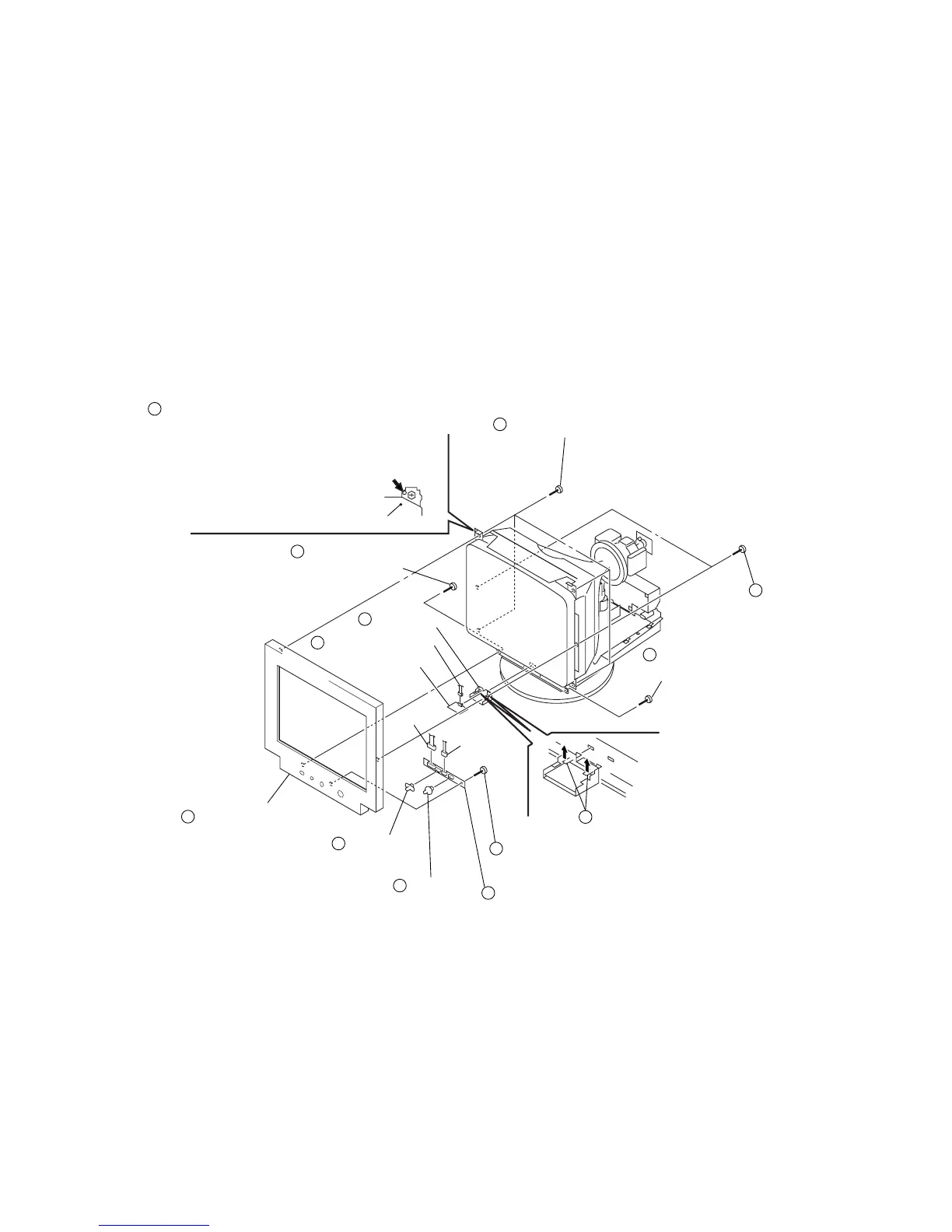
1-4. BEZEL ASSEMBLY, H6 BOARD REMOVAL
2
1
Four tapping screws (5)
5
Bezel assembly
7
Joy stick
Input slide
button
4
Screw
(+BVTP 4 x 16)
4
Screw
(+BVTP 4 x 16)
3
Screw
(+BVTP 4 x 16)
Three screws
(+BVTP 3 x 10)
10
Two claws
9
H6 board
12
Magnetic
MIU-221D sensor
11
L1 blacket
CN1400
CN1500
CN1401
Picture tube shield
Before removing the bezel assembly, secure
the picture tube by attaching two screws to
the picture tube shield at the positions shown
with an arrow (diagonal two places) to prevent
the picture tube from falling.
(Use the screws +BVTT 4 x 8 that fix EMI shield.)
6
8

Other manuals for Sun Microsystems GDM-5510

Questions and Answers:

Question and Answer IconNeed help?

Do you have a question about the Sun Microsystems GDM-5510 and is the answer not in the manual?

Sun Microsystems GDM-5510 Specifications

General IconGeneral
BrandSun Microsystems
ModelGDM-5510
CategoryMonitor
LanguageEnglish

Related product manuals