GDM-5510 (E) 3-3
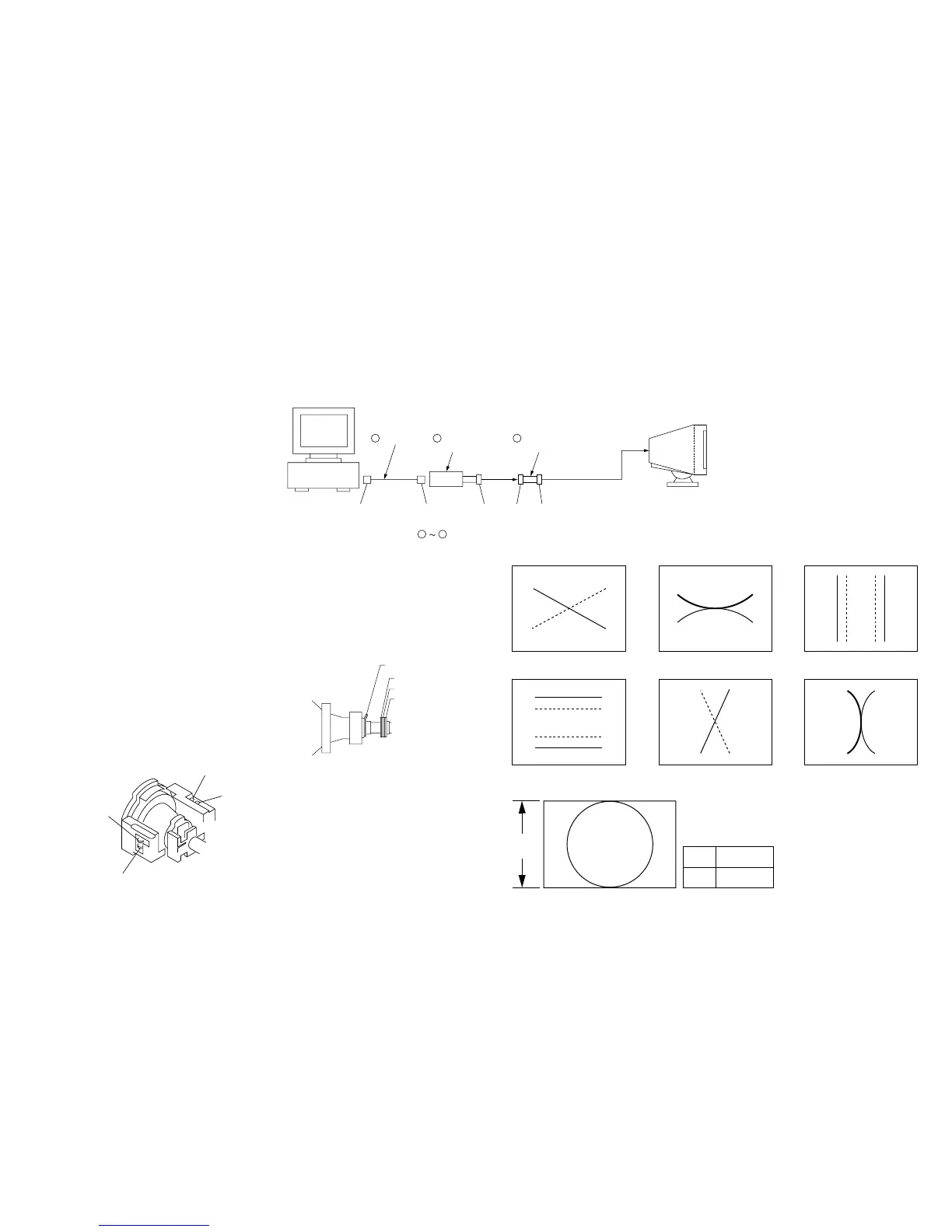
IBM AT Computer
as a Jig
1-690-391-21
1
A-1500-819-A
Interface Unit
2
*The parts above ( ) are necessary for DAS adjustment.
1
3
D-sub
(9 Pin [female])
mini Din
(8Pin)
4 Pin
3-702-691-01
Connector Attachment
3
To BUS CONNECTOR
4 Pin 4 Pin
• Convergence Specification
B
A
A
0.20 mm
B
0.24 mm
V
XBVXCV
B
R
B
R
R
B
B
R
R
BBR
TLV
TLH
YBHYCH
R B
R B
H.TRAP
TB-PIN
TLH
XCV
Purity
4-pole magnet
6-pole magnet
2-pole magnet
Connect the communication cable of the computer to the connector located on the D board. Run the service software and then follow the instruction.
• Convergence Rough Adjustment
(1) Display white crosshatch pattern.
(2) Pile the convex parts of 6-pole magnet for convergence together.
(3) Roughly adjust H.CONV and V.CONV with 4-pole magnet.