STARTING
The first
step
in testing
the Starting
System is to
make a Battery
Performance Test,
since a good
bat-
tery must
be used
to test the
starter
motor, cables
and solenoid. State
of a vehicle
battery
can be
determined in the
BATTERY
LOAD mode of the
tester.
With
a
known good battery,
the starter
motor,
cables, and starter
solenoid can be
checked
by
per-
forming the
Starting System Test.
The Starting
System test should be
made
with a
serviceable battery or the test
results could be
in
error.
The engine is cranked
with the
ignition sys-
tem disabled so
that
the
engine will
not start.
The test
procedure consists of
cranking the
engine
for 15
seconds while storing the
AMPS
DISPLAY
values for starter current
draw
and
the
tester VOLTS
DISPLAY
values for cranking voltage.
Good
starting systems will read: Starter
current not to
exceed
the maximum
specified for the
vehicle being
tested.
Cranking voltage on 12 volt
systems: some
vehicles are
rated
at
9.6 volts
minimum, some at 9.0
volts minimum. On 6 volt
systems: 4.8
volts is the
minimum.
Refer
to
manufacturer’s
specifications.
Starting System
Area Test
The STARTING
SYSTEM test
mode
displays volt-
age and current
readings
and gives a GOOD/BAD
indication of
starter
current draw. In this
mode, the
VAT
60 stores
peak current
and the lowest voltage
values until
the
testing
is complete
and
the values
can be displayed.
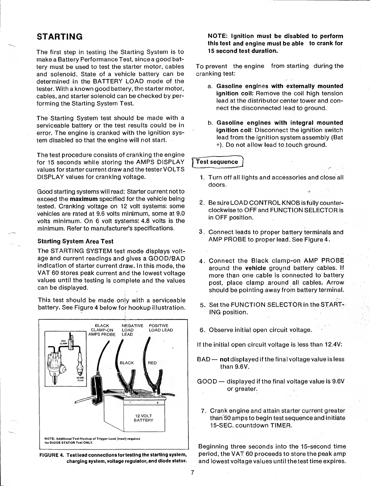
This
test should
be made
only with a
serviceable
battery.
See Figure
4 below for hookup illustration.
FIGURE
4. Test lead
connections for
testing the
starting
system,
charging system, voltage
regulator,
and diode
stator.
NOTE:
Ignition must
be disabled to perform
this test
and
engine
must be
able
to crank for
15 second test
duration.
To
prevent the
engine
from starting during the
cranking
test:
a.
Gasoline engines with externally mounted
ignition coil: Remove
the coil high
tension
lead at the distributor center tower and con-
nect the
disconnected lead
to
ground.
b. Gasoline engines with integral mounted
ignition
coil:
Disconnect
the ignition
switch
lead from the ignition system assembly (Bat
+). Do not allow lead to .touch ground.
Test sequence
j
1. Turn off
all
lights and accessories
and
close all
doors.
2. Be
sure LOAD CONTROL
KNOB is fully counter-
clockwise
to
OFF
and FUNCTION SELECTOR
is
in
OFF
position.
3
.
Connect leads
to proper battery terminals and
AMP PROBE
to
proper lead. See Figure
4
.
4.
Connect
the Black clamp-on
AMP PROBE
around the vehicle
ground battery cables.
If
more
than one cable is
connected to battery
post, place clamp
around all cables.
Arrow
should be
pointing away from
battery terminal.
5. Set
the FUNCTION
SELECTOR in the
START-
ING position.
6.
Observe initial
open
circuit voltage.
If the
initial
open
circuit voltage is less than
12.4V:
BAD
—
not displayed if the final
voltage value is less
than
9.6V.
GOOD
—
displayed if the final voltage value
is 9.6V
or greater.
7.
Crank
engine and attain starter
current greater
than 50 amps
to
begin test sequence
and
initiate
15-SEC. countdown TIMER.
Beginning
three seconds into
the 15-second
time
period,
the VAT
60
proceeds to store the peak
amp
and
lowest voltage values until the test
time expires.
7
 Loading...