18
4.3 LCD Display Icons
The operation and display panel, shown in below chart, is on the front panel of the inverter. It includes four
indicators, four function keys and a LCD display, indicating the operating status and input/output power information.
Chart 4-2 Function Buttons
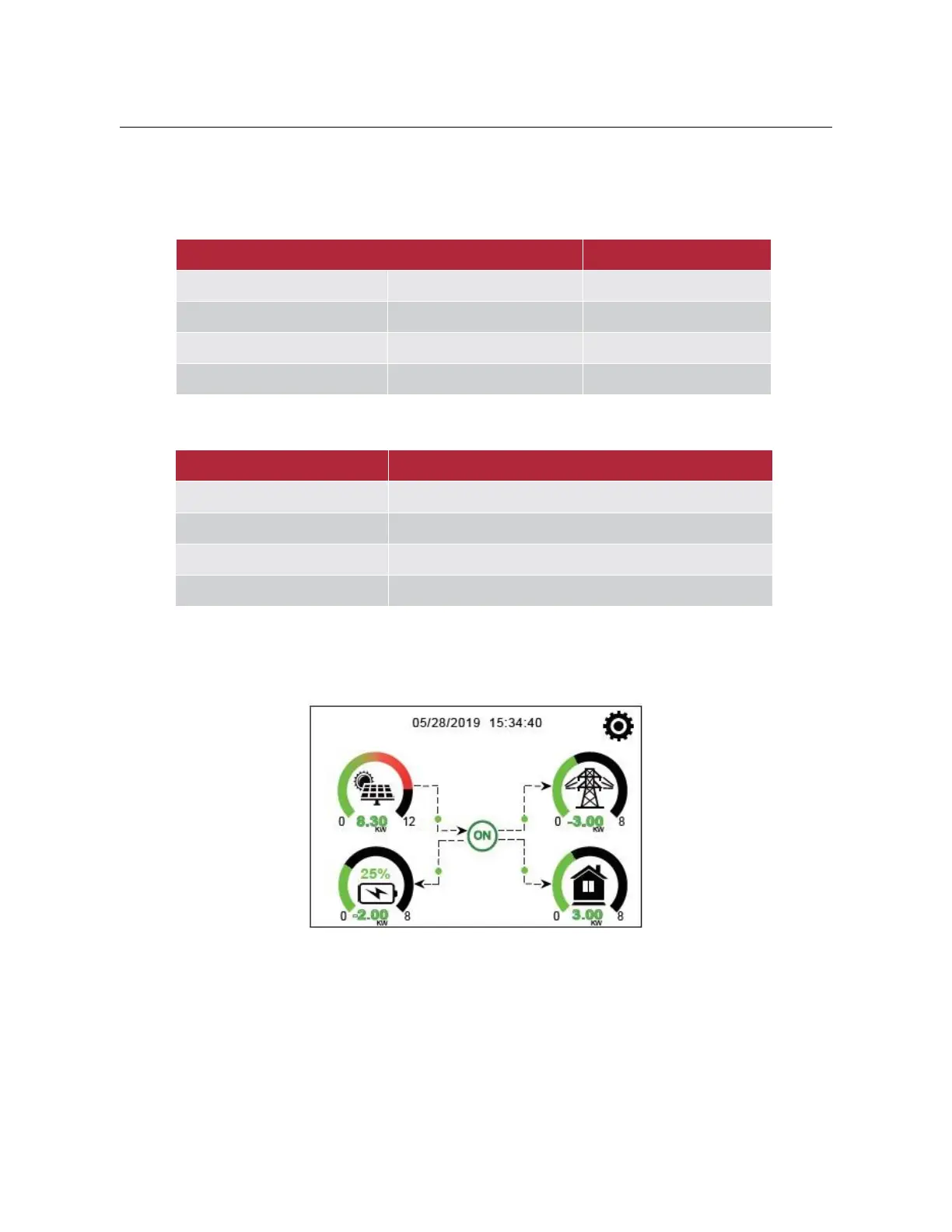
4.3.1 Main Screen
The LCD is touch screen, below screen shows the overall information of the inverter.
(1)
The icon in the center of the home screen indicates that the system is Normal operation. If it turns into
ŗFRPP)a)Ř it means the inverter has communication errors or other errors, the error message will
display under this icon (detail error info can be viewed in the chapter 5.3).
(2)
At the top of the screen is the time.
(3)
System Setup Icon, press this set button, you can enter into the system setup screen which including Basic
Setup, Battery Setup, Grid Setup, System Work Mode, Generator port use, advanced function and Li-Battery info.
(4)
The main screen showing the info including Solar, Grid, Load and Battery. ,WŖV also displaying the energy flow
direction by arrow. When the power is approximate to high level, the color on the panels will changing from green