User Manual 6 Electrical Connection
23
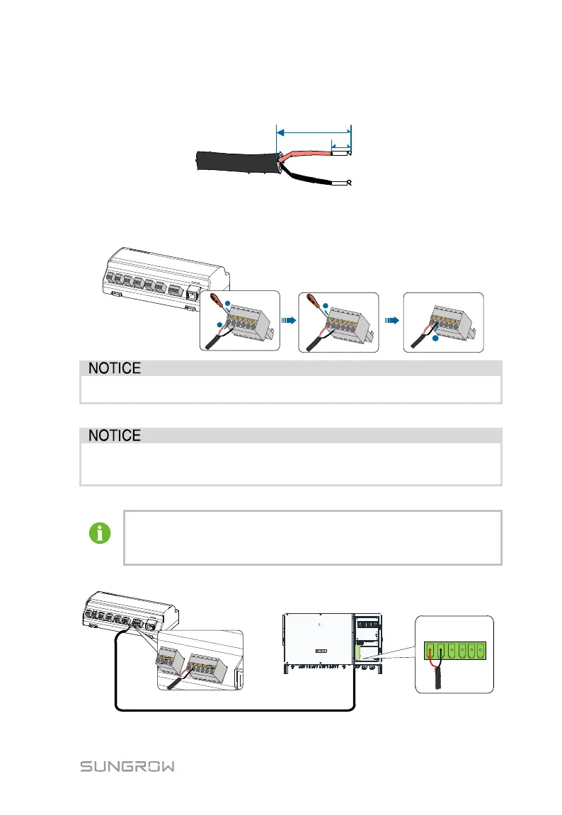
Step 2 Strip the cable jacket and insulation layer with a wire stripper by about
15mm and 8mm to 10mm respectively.
Step 3 Connect the stripped cable to the RS485 ports of the Logger1000, as shown
in the figure below.
RS485A is connected to port A while RS485B is connected to port B.
The RS485 communication cable must be the shielded twisted pair with
the shielding layer single-point grounded.
When a multi-core multi-strand copper wire cable is used, crimp an
appropriate euro style terminal at the communication cable head and
then connect it to the RS485 port of the Logger1000.
Step 4 Logger1000 is connected to the inverter.
Logger1000
Inverter
A1 B1 PE A1 B1PE
RS485
RJ45 port connection