User Manual 9 Grid Dispatching Function
59
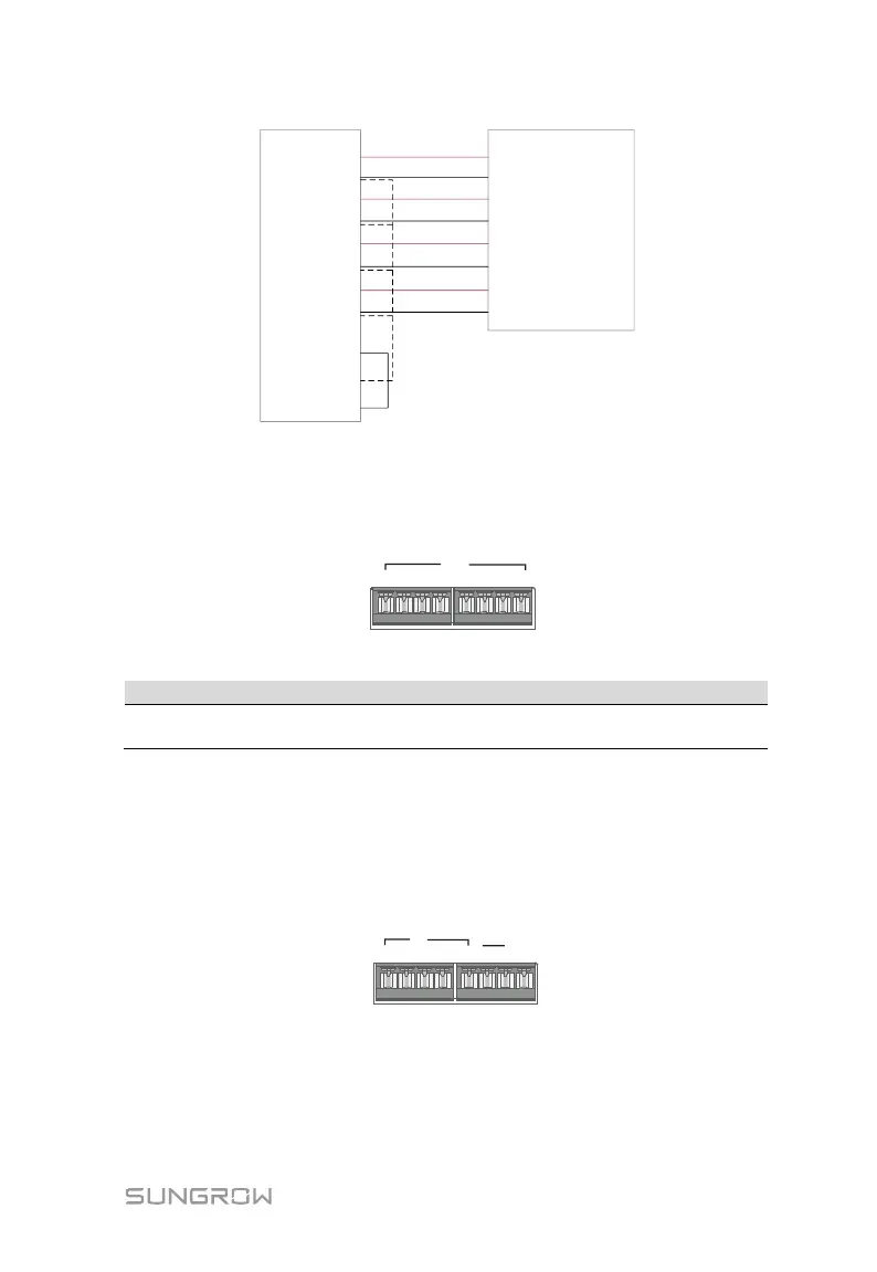
Logger1000
Ripple Control Receiver
1+
1-
2+
2-
3+
3-
4+
4-
DI
24 OUT-
24 OUT+
DI 1+
DI 1-
DI 2+
DI 2-
DI 3+
DI 3-
DI 4+
DI 4-
9.2.2 Analog Control Interface
The analog control interfaces are at the bottom of the Logger1000, and a sum of 4
analog input ports are provided, as shown in the figure below.
1+ 1- 2+ 2-
AI/DI
3+ 4+3- 4-
Tab. 9-2 Analog control interface signal definition
1+, 1-, 2+, 2-
3+, 3-, 4+, 4-
4 analog input channels
The Logger1000 supports 4 inputs of 4~20mA analog currents or 4 inputs of 0~
10V analog voltage.
9.2.3 DRM Control Interface
The DRM control interface are located at the bottom of the Logger1000, as shown in
the figure below.
The DRM interface works together with DI1~DI4 to achieve the DRM function.
Wiring between the Logger1000 and the DRED is as follows: