40
When the switch is turned to A-T-B position, the loop feeders are connected with the
transformer be energized.
When the switch is turned to A-T position, only one side of the transformer loop (A bushing)
is connected with the transformer be energized.
When the switch is turned to B-T position, only one side of the transformer loop (B bushing)
is connected with the transformer be energized.
When the switch is turned to A-B position, both sides of the transformer loop (A and B
bushings) are connected with the transformer de-energized.
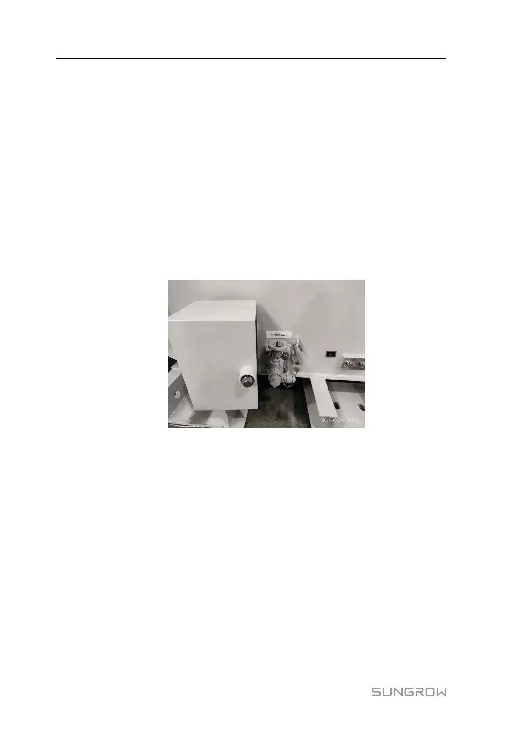
8.15 Oil Draining Valve
Close to the base of the transformer, there is a valve which is used for the oil sampling and
drainage as below figures show. The drainage valve might be locked in a box which need to
be accessed with a key.
figure 8-24 Oil drainage valve
If the transformer is transported with a full oil tank, drain some oil from the transformer after
the product is transported to the site.
Drain Oil
1 Ensure that the drain valve is closed.
2 Remove the cover plate of the drain valve.
3 Remove the cover plate of the drain valve.
8 Components and Accessories User Manual