10 Operation of LCD Display User Manual
78
Uin**
Enter Q(P) regulation mode
when grid voltage is above
Uin
105% 100~110% 1%
Uout**
Exit from the Q(P) regulation
mode when grid voltage is
below Uout
100% 90~100% 1%
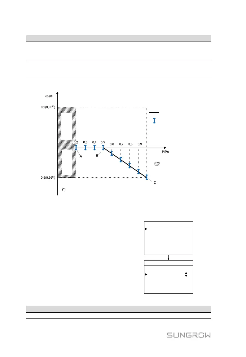
*PA < PB≤ PC ** Uin>Uout
Inductive
Capacitive
Default Curve
Deviation
No Regulation
cosg = ± 0,98
Depends on the capacity of the inverter.
Fig. 10-5 Reactive Power Regulation Curve in “IT” Q(P) Mode
Italy/Thailand “Q(U)” Mode
The reactive power ratio changes with the grid
voltage.
Select Q(U) mode and Press
to enter the
“Run-para-Q(U)” sub-menu.
Press
to move the cursor; Press
to enter the
editing mode, then the selected parameter will be
shaded.
Press
to increase one-step value; Press
to
decrease one-step value.
Press ENTER to confirm the setting and exit from
the editing mode.
Run-param-Q ( U ) P3/4
Qmax 100.0%
V2i 090. 0%
V1i 092. 0%
V1s 108. 0%
V2s 110. 0%
Pin 020.0%
Run-param-Q ( U ) P4/4
Curve [A]
Pout 009.0%
Tab. 10-9 Italy/ Thailand “Q(U)” Mode Parameters Explanation
Grid voltage at point D (in %)
 Loading...