Step 3 Lead the cable through the cable
gland.
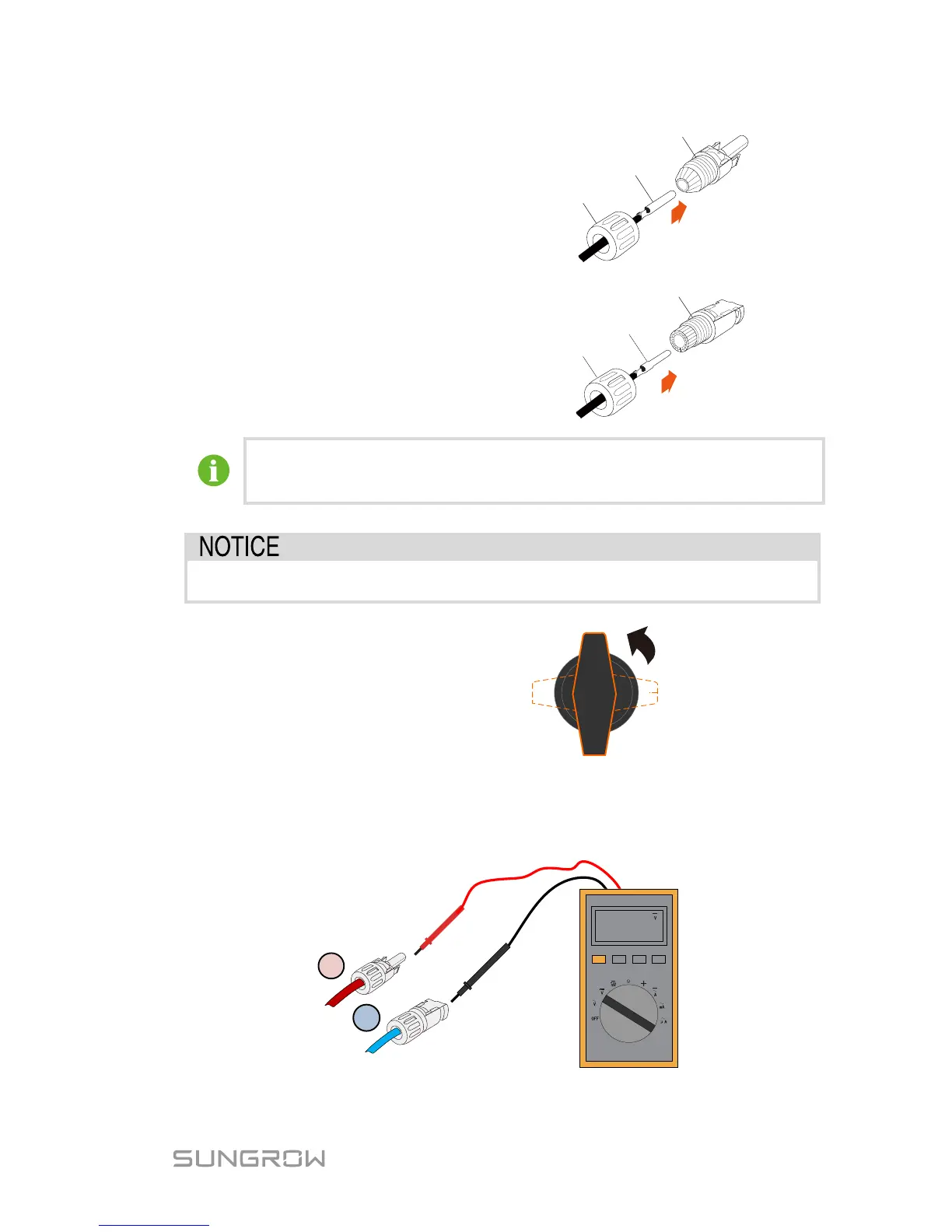
Step 4 Insert the crimp contact into the
insulator until it snaps into place.
Then pull gently to make sure it is
secured.
Step 5
Screw the cable gland to insulator
with tightening torque 2.5…3 Nm.
Crimp Contact
Positive Insulator
Cable Gland
Negative Insulator
Crimp Contact
Cable Gland
For more assembly and connection instruction, please visit the webpage
of the device manufacturer.
Step 6 Check to make sure the polarities of PV strings are correct.
The inverter will not function properly if the DC polarities are reversed.
Step 7 Disconnect the DC switch.
Step 8 Check the connection cable of PV string for the correct polarity and that
circuit voltage does not exceed the inverter input limit 1100V,
even under the lowest operating temperature.
 Loading...