Do you have a question about the SunSynk ECCO SUN-5K-SG05LP1-EU and is the answer not in the manual?
Safety guidelines for device usage and ensuring manual is included and understood.
Explanation of warning and caution symbols indicating potential hazards.
Essential instructions for installation, operation, and maintenance to prevent hazards.
Guidelines for proper disposal of electrical devices according to regulations.
Overview of the Sunsynk Ecco Hybrid Inverter's multifunctional capabilities.
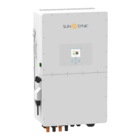
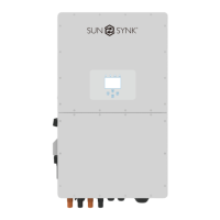
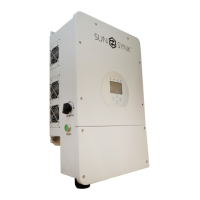
Specifications detailing the physical size of the inverter and its mounting bracket.
Detailed list of interactive, compatible, configurable, and secure features.
Illustration showing the basic application of the inverter in a complete system.
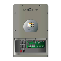
List and images of all components included in the inverter package.
Guidelines for choosing a suitable and safe mounting location for the inverter.
Step-by-step instructions for securely mounting the inverter on a wall.
Requirements for DC over-current protection and cable specifications.
Steps and cautions for connecting the battery to the inverter, including polarity.
Explanation of various ports (BMS, CAN, RS485, DRM) and DIP switch functions.
Recommended components and diagrams for DC battery protection.
Procedure for connecting a lithium battery, including communication cables.
Important notes on master/slave configurations and BMS communication.
Instructions for connecting the battery temperature sensor.
Steps for connecting the inverter to AC power, including breaker recommendations.
Diagram and components for installing an AC surge protector.
Safety and cable size requirements for connecting PV modules.
Parameters to consider when selecting PV modules for the inverter.
Steps for wiring PV modules and essential safety warnings.
Diagram illustrating solar surge protection and fuse installation.
Procedure for installing the CT coil for zero export functionality.
Diagram showing CT coil connection and correct polarity for function.
System connection diagram for the CHNT meter.
Importance and procedure for establishing the earth connection.
Information on neutral bonding and hybrid system earth requirements.
Diagrams illustrating different inverter wiring configurations.
Diagram for connecting multiple inverters in single-phase parallel.
Diagram for connecting multiple inverters in three-phase parallel.
Diagram showing typical application with a diesel generator.
Procedure for turning the inverter system on and off.
Explanation of the inverter's LCD screen and status indicators.
Meaning of the different LED lights indicating system status.
Description of the functions assigned to each button on the interface.
Flowchart illustrating how to navigate through the inverter's LCD menus.
Accessing the home page to view system status and basic information.
How to access and interpret detailed system status information.
Diagram explaining the flow of power within the solar system.
Guide to accessing the main setup menu via the gear icon.
Setting system time, date, company name, beeper, and auto-dim.
Procedures for factory reset, system diagnostics, and lock code management.
Setting battery parameters like type, capacity, charge, and discharge rates.
Configuring generator input for charging the battery bank.
Configuring inverter shutdown, low battery warnings, and restart thresholds.
Specific steps and considerations for setting up lithium-ion batteries.
Programming specific times for battery charging and discharging.
Explanation of modes like Zero Export and Solar Export for power management.
Configuring grid mode, frequency, and voltage parameters.
Setting up protection parameters for grid voltage and frequency.
Adjusting inverter active and reactive power based on grid voltage.
Settings for adjusting reactive power and power factor.
Setting up inverters for parallel operation as master or slave.
Important considerations for parallel inverter setup, firmware, and breakers.
Common questions and consequences related to parallel inverter operation.
Configuration options for Demand Response Management Systems.
Configuration for system self-check, island mode, and BMS error handling.
Viewing daily, monthly, and yearly solar energy production data.
Viewing daily, monthly, and yearly grid power import/export data.
Settings for integrating wind turbines as an input source.
Configuring auxiliary loads and generator peak shaving.
Details on Gen Input and Aux Load Output modes for smart loads.
Configuration for 'On Grid always on' and Micro Inverter Input.
Diagram illustrating the basic operating mode of the inverter.
Diagram showing the operating mode when connected to a generator.
Diagram illustrating the operating mode with a smart load connected.
Diagram showing the operating mode for AC coupling.
Overview of fault codes and required information for support.
Detailed list of fault codes and their corresponding troubleshooting solutions.
Comprehensive list of fault codes and their associated instructions.
Step-by-step guide for powering the inverter on and off.
Essential checks for solar, grid, and battery during inverter commissioning.
Explanation of GDFI fault and related impedance checks.
Recommended maintenance tasks for ensuring inverter longevity.
Pinout details for CAN, RS485, and RS232 communication interfaces.
Recommendations and specifications for Residual Current Devices (RCDs).
Information on connecting data loggers for internet and monitoring.
| Model | SUN-5K-SG05LP1-EU |
|---|---|
| Category | Inverter |
| Rated Output Power | 5kW |
| Max. PV Input Power | 6.5kW |
| Max. PV Input Voltage | 500V |
| Number of MPPTs | 2 |
| Max. Input Current per MPPT | 13A |
| AC Output Voltage | 230 V |
| AC Output Frequency | 50/60Hz |
| Grid Connection Type | Single Phase |
| Battery Voltage | 48V |
| Max. Charging Current (PV) | 100A |
| Max. Charging/Discharging Current | 100A |
| Max. Output Power | 5kW |
| Nominal AC Voltage | 230 V |
| Max. DC Input Power | 6500 W |
| Efficiency (Max) | 97.6 % |
| Max Efficiency | 97.6 % |
| Protection Rating | IP65 |
| Weight | 18 kg |
| Input Voltage Range | 120-450V |
| Operating Temperature Range | -25°C to +60°C |
| Communication | RS485, Wi-Fi |