EasyManua.ls Logo

SunSynk SUNSYNK-25K-SG01HP3-EU-BM2 User Manual

SunSynk SUNSYNK-25K-SG01HP3-EU-BM2
76 pages
To Next Page IconTo Next Page
Page #1 background imageLoading...
Page #1 background image
v.19 (08/21/23)
SUNSYNK-25K-SG01HP3-EU-BM2
SUNSYNK-30K-SG01HP3-EU-BM3
SUNSYNK-40K-SG01HP3-EU-BM4
SUNSYNK-50K-SG01HP3-EU-BM4
THREE-PHASE
HYBRID INVERTER
PLEASE RETAIN FOR
FUTURE REFERENCE
USER MANUAL
www.sunsynk.com
sales@sunsynk.com
customerservices@sunsynk.com

Table of Contents

Question and Answer IconNeed help?

Do you have a question about the SunSynk SUNSYNK-25K-SG01HP3-EU-BM2 and is the answer not in the manual?

SunSynk SUNSYNK-25K-SG01HP3-EU-BM2 Specifications

General IconGeneral
BrandSunSynk
ModelSUNSYNK-25K-SG01HP3-EU-BM2
CategoryInverter
LanguageEnglish

Summary

PREFACE

SAFETY

General Safety

General safety instructions for using the inverter.

Symbols/Safety Signs

Explanation of safety symbols and signs used in the manual.

Safety Instructions

Product Disposal

Guidelines for proper disposal of the product and accessories.

PRODUCT INTRODUCTION

System Overview

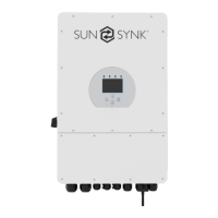
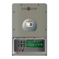
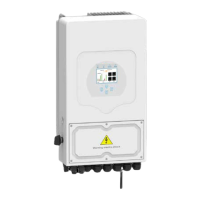
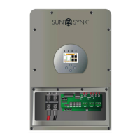
An overview of the inverter's components and connections.

Product Size

Mounting bracket

Illustration of the mounting bracket for the inverter.

Basic System Architecture

Product Handling Requirements

Instructions for safely handling the inverter during installation.

INSTALLATION

Parts List

List of components included in the inverter package.

Selecting the Mounting Area

Mounting the Inverter

Function Port Definition

Battery Connection

Grid and Backup Load Connection

PV Connection

PV Module Selection

Guidelines for selecting appropriate PV modules for the inverter.

PV Module Wiring

Connecting the CT Coil

Meter Connection

CHNT Meter

Wiring diagram for connecting the CHNT meter.

CHNT Meter with CT Coil

Earth Connection (MANDATORY)

Wiring System for Inverter

Wiring Diagram

Typical Application of Diesel Generator

Three Phase Parallel Connection

OPERATION

Switching ON/OFF

Procedure for turning the inverter on and off.

LED indicators

Explanation of the inverter's LED status indicators.

Function buttons

Description of the inverter's function buttons and their actions.

LCD operation flow chart

Home page

Status Page

Displays the status of Load Power, Grid Power, Inverter Power, etc.

System Flow Page

Setup Page

BASIC

Access to basic setup options like time and company name.

BATTERY

Access to battery configuration settings.

GRID

Access to grid connection and configuration settings.

SYSTEM MODE

Access to system mode and timer settings.

ADVANCE

Access to advanced settings like paralleling and wind turbines.

AUX LOAD

Access to auxiliary load and smart load settings.

FAULT CODES

Access to the fault code register.

LI BMS

Access to Lithium Battery Management System settings.

Basic Setup: Time and Display Settings

Set Time (Clock)

Instructions for setting the inverter's time and date.

Set Company Name / Beeper / Auto dim

Configure company name, beeper, and LCD auto dim settings.

Factory Reset and Lock Code

Inverter Remote Control

Battery Setup Page

Configuration options for battery type and settings.

Generator & Battery Page

Battery Discharge Page

State of Charge

Setting Up a Lithium Battery

Guide for configuring lithium-ion battery settings.

Li BMS

Program Charge & Discharge Times

Grid Supply Page

Paralleling Inverters Advanced Settings

Connecting the DRM's

Solar Power Generated

Grid Power

Advanced Settings for Wind Turbines

Advanced Settings for Auxiliary Load

OPERATION MODES

Mode I: Basic

Basic operating mode of the inverter.

Mode II: With Generator

Operating mode with a connected generator.

Mode III: With Smart-Load

Operating mode with smart load functionality.

Mode IV: AC Couple

Operating mode for AC coupled systems.

FAULT CODES

COMMISSIONING

Start-Up / Shutdown Procedure

Step-by-step guide for powering the inverter on and off.

Inverter Commissioning Info

Information and checks required after powering up the inverter.

GDFI Fault

MAINTENANCE

APPENDIX A

Definition of RJ45 Port Pin for BMS1

Pinout details for the BMS1 RJ45 port.

Definition of RJ45 Port Pin for BMS2

Pinout details for the BMS2 RJ45 port.

Definition of RJ45 Port Pin for Meter

Pinout details for the Meter RJ45 port.

Definition of RJ45 Port Pin for RS485

Pinout details for the RS485 RJ45 port.

WIFI/RS232

Details for connecting the WIFI/RS232 datalogger.

APPENDIX B

Split Core Current Transformer (CT) dimension: (mm).

Dimensions and specifications for the CT.

CONTACT US

Related product manuals