Installation
900285-00 11/2014
Innovative Hearth Products
Superior
TM
DRT3000 Series Direct-Vent Gas Fireplaces
32
Table 20: Venting Components Required for Various Exterior Wall Thicknesses, when using Typical Termination Kits
Vent Components Required Exterior Wall Thickness
Termination Kit Only 6–9 1/4” (152–235 mm)
Termination Kit and 6” Vent Section (SV4.5L6) 10 3/4–14” (273–356 mm)
Termination Kit and 12” Vent Section (SV4.5L12) 16 3/4–20” (426–508 mm)
Termination Kit and Telescopic Section (SV4.5L12) 11 3/4–20” (299–508 mm)
Horizontal Vent Figures/Tables
NOTE: Secure Vent
®
rigid vent pipe and terminal are shown in the figures. Secure Flex
®
flexible vent pipe and
terminal may also be used.
NOTE: Two (2) 45° elbows may be used in place of one (1) 90° elbow. The same rise to run ratios, as shown in the
venting figures for 90° elbows, must be followed if 45° elbows are used.
NOTE: Maintain the horizontal/inclined run in a straight (no dips), slightly elevated plane. The recommended incline
is approximately 1/4” per 1 ft (20 mm per 1 m) horizontal, in a direction away from the fireplace. Smaller rise per
foot run ratios are acceptable all the way to at or near level. Use a carpenter’s level to measure from a constant
surface and adjust the support straps as necessary.
NOTE: SV4.5VF (Secure Vent), SF4.5VF (Secure Flex) firestop/spacer must be used any time vent pipe passes
through a combustible floor or ceiling. SV4.5HF (Secure Vent), SF4.5HF (Secure Flex) firestop/spacer must be used
any time vent pipe passes through a combustible wall.
WARNING
Do not join separate sections of concentric flexible vent together.
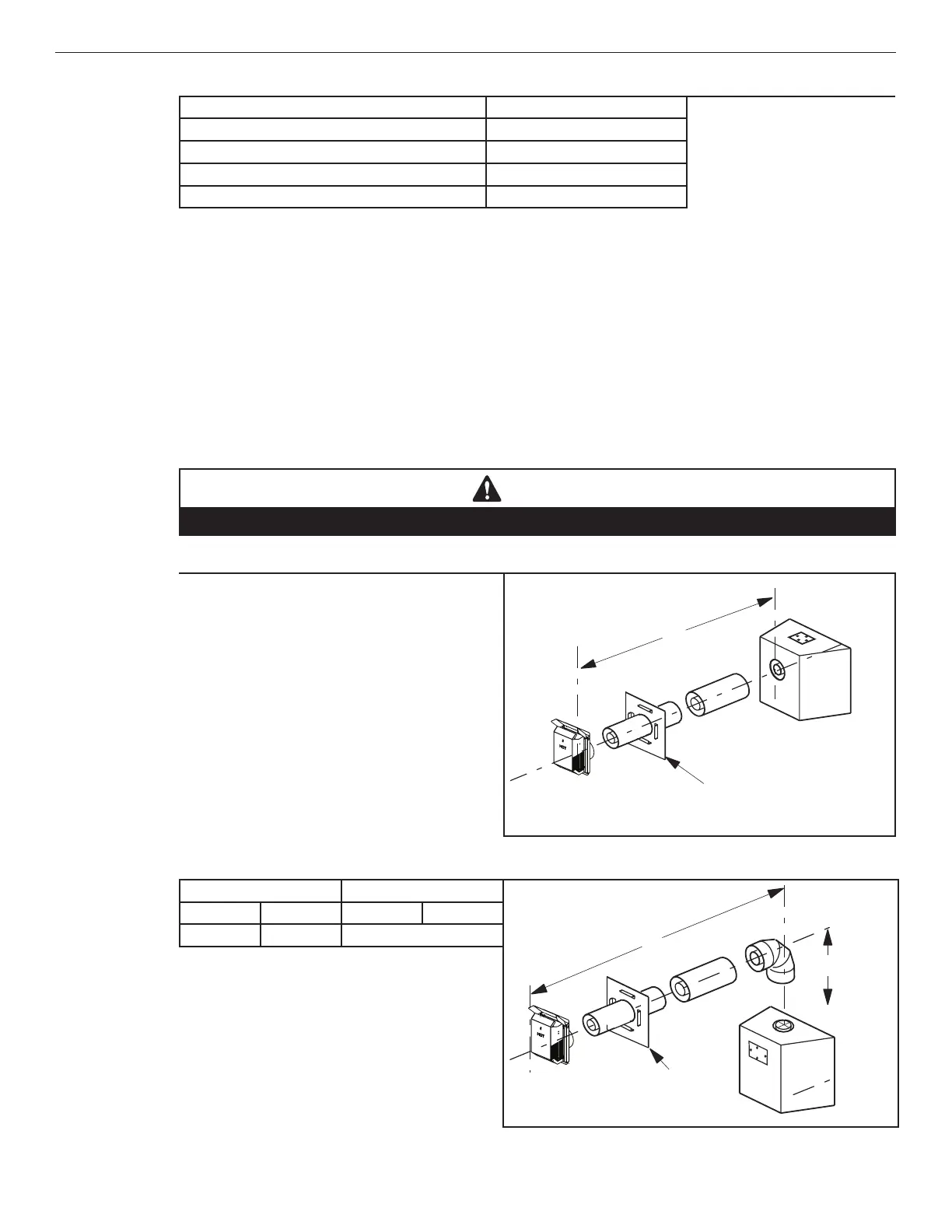
Table 21: Rear Vent—No Elbows
See Table 21 as an aid in venting component selection for a
particular range of exterior wall thicknesses.
Note: “H” is horizontal distance from rear of unit to outer wall
surface
Note: When venting Rear Horizontal with slip collar and
termination only, install base vent restrictor with the
breakwway portion raised. On 33” Models, use the 3” base
at 6’ instead of the 2 1/2” breakaway.
H = 28 in. (711 mm) Maximum
**When using Secure Flex, use
Wall Firestop/Spacer SF4.5HF
When using Secure Flex
®
, use
wall firestop/spacer SF4.5HF, and
install venting with a minimum of
12” rise. (Page 35).
H = 21” (533 mm) maximum
27 1/2”
(699 mm) to outside
of termination
Table 22: Top Vent—One 90° Elbow, Elbow Connection at Fireplace
H Maximum V Minimum
Wall
firestop/
spacer
SV4.5HF *
When using Secure Flex
®
, use
wall firestop/spacer SF4.5HF.
*
H
V
feet meters feet meters
3 0.91 Elbow only
Install the U-shaped vent restrictor in any vent run with
more than 4 ft of vertical rise. See Page 21 for more
information.
See Table 21 as an aid in venting component selection for a
particular range of exterior wall thicknesses.
NOTE: Only in top vent where elbow is connected at fireplace collar
is it allowed to count elbow as 1 ft. vertical (V) rise.