Installation
900285-00 11/2014
Innovative Hearth Products
Superior
TM
DRT3000 Series Direct-Vent Gas Fireplaces
37
2. Wire the control switch within the millivolt control circuit using the 15 ft of 2-conductor wire supplied with
the unit (Figure 33).
NOTE: The supplied 15 ft of 2-conductor wire has one end of each conductor connected to the gas valve circuit and
the other end of each conductor placed loose inside the bottom compartment.
CAUTION
In millivolt systems, do NOT connect a wall switch to a 120 V power supply.
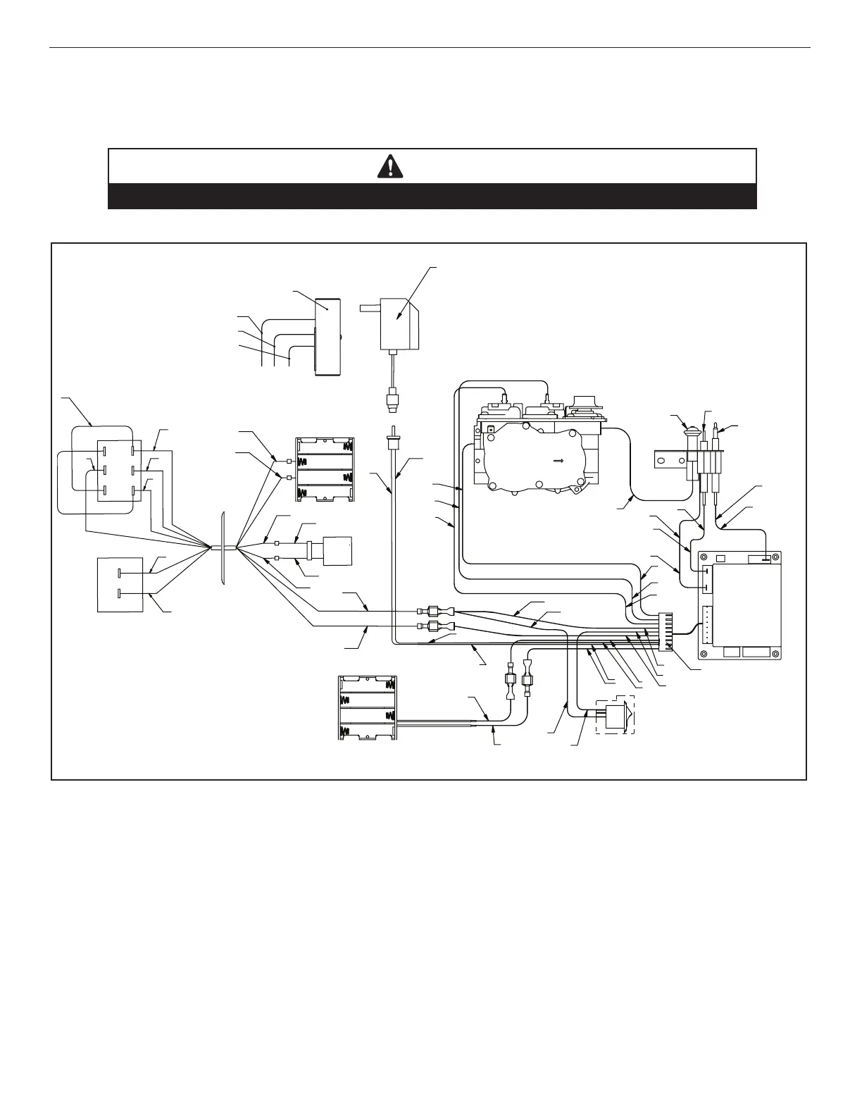
Figure 31: Wiring Diagram—Electronic Gas Valves
B = BLACK
BR = BROWN
GY = GRAY
PU = PURPLE
R = RED
BL = BLUE
G = GREEN
O = ORANGE
W = WHITE
Y = YELLOW
WIRING COLOR CODE
ELECTRONIC PILOT ASSEMBLY
HOOD
PROFLAME VALV E
PROFLAME
DFC BOARD
SPLIT
FLOW
BATTERY
HOLDER
BATTERY
HOLDER
ON/OFF WALL
SWITCH
HI/LOW
SWITCH
IGNITER ROD
CPI SWITCH
OFF (O) = INTERMITTANT PILOT MODE
ON (–) = STANDING PILOT MODE
DFS WIRE HARNESS
PILOT GROUND WIRE
SPARK WIRE CABLE
PILOT TUBE
FLAME SENSOR
PILOT
SENSOR
CABLE
AC/DC
POWER
ADAPTOR
JUNCTION
BOX
120V AC
HOT
NEUTRAL
GROUND
BL
2B 1B
2A
21
1A
R
O
B
1
2
G
W
BL
BL
O
O
R
R
G
W
B
B
W
G
R
W
B
Y
G
O
G
W
R
BL
B
BL
W
G
G
Y
O
Y
B
B
B
R
B
Electronic Wiring
One of the following optional controls must be used:
• ON/OFF Wall Switch,
• Thermostat, or
• Remote Control.
See the Operation section on Page 50 for more details.
NOTE: Electronic models must be connected to the main power supply.
1. Route a 3-wire, 120 Vac, 60 Hz, 1 ph power supply to the fireplace junction box.
2. Remove the electrical inlet cover plate from the side of the unit by removing the plate’s securing screws
(Table 8).
3. If unit is not supplied with a strain relief, remove the cover plate knockout. Then, feed the power supply wire
through the knockout opening and into the unit junction box.
4. Connect the black power supply wire to the lower outlet’s red pigtail lead (Figure 32 and Figure 33). Connect the
white power supply wire to the outlet’s common terminal.