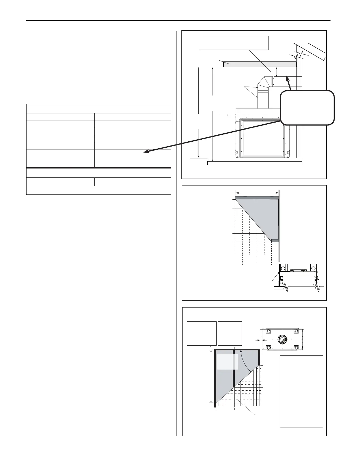
Figure 10: Side Wall Clearances
11
NOTE: DIAGRAMS & ILLUSTRATIONS ARE NOT TO SCALE.
Figure 9: Mantel Clearances
4" (102 mm) above any horizontal/inclined vent component.
See Step 1 ("FRAMING") on Page 12 for clearance requirements to
nailing flanges on each side of unit and any adjacent screw heads.
The appliance should be mounted on a fully supported base extending
the full width and depth of the unit. The appliance may be located on
or near conventional construction materials; however, if installed on
combustible materials, such as carpeting, vinyl tile, etc., a metal or wood
barrier covering the entire bottom surface must be used.
Min. Height of Combustible Enclosure
To provide for the lowest possible combustible enclosure (or shelf)
surface, the venting should be routed in a way to minimize obstructions
to the space above the appliance. Do not insulate the space between the
appliance and the area above it (see Figure 8).
Wall Finishes / Surrounds / Mantels
Note: Combustible wall finish materials and/or surround materials must
not be allowed to encroach the area defined by the appliance front faces
(black sheet metal). Never allow combustible materials to be positioned
in front of or overlapping the appliance face. See Pages 33 and 34.
Non-combustible materials, such as surrounds and other appliance trim,
may be installed on the appliance front face with these exceptions: they
must not cover any portion of the removable glass panel.
Vertical installation clearances to combustible mantels vary according
to the depth of the mantel (see Figure 9). Mantels constructed of non-
combustible materials may be installed at any height above the appliance
opening.
Note: Use high-temperature paint (rated 175°F or higher) on the under-
side of the mantel.
NOTE: Attic insulation shield (H3908, see Page 36) must be
installed when blown or loose-fill insulation is used, and is
required for all attic installations.
7 (178)
2
(51)
4
(102)
6
(152)
8
(203)
10
(254)
12
(305)
9 (229)
13 (330)
17 (432)
15 (381)
11 (279)
Side View
Inches
(millimeters)
Mantel Depth
Minimum Distance to Unprotected Side Wall
Top of Appliance
Distance from top of appliance
to bottom of mantel
INNOVATIVE HEARTH PRODUCTS • SEE-THROUGH DIRECT-VENT GAS FIREPLACES (DRT63STTEN/P) • INSTALLATION INSTRUCTIONS
MINIMUM CLEARANCES TO COMBUSTIBLES
Appliance and Vent Clearances
The appliance is approved with zero clearance to combustible materials
on both sides (as detailed in Table 5), with the following exceptions:
• When the unit is installed with one side flush with a wall, the wall on the
other side of the unit must not extend beyond the front edge of the unit.
• In addition, when the unit is recessed, the side walls surrounding the
unit must not extend beyond the front edge of the unit (see Figure 2
on Page 6).
Figure 8: Min. Height of Combustible Enclosure
Min. 2 ft vertical
vent section
and one 90-degree
elbow required
Combustible
Enclosure/Shelf
Min. 4"
(102 mm)
90" (2287 mm)
minimum
Indoor/Outdoor
91.5" (2324 mm)
minimum
Indoor/Outdoor
Top of
Fireplace
2 x 4
Combustible materials
are allowed in gray “safe
zone” illustrated here.
Combustible walls are
shown in black.
Protected wall is shown
in white.
Combustible material
may project beyond
the side of the fireplace
opening if it is within
the gray "safe zone"
illustrated here.
0.5"
(13 mm)
5 in
(127 mm)
8.25"
14"
12 in
(305 mm)
17 in
(432 mm)
Top View of Fireplace
45°
Protected wall
shown in white
Gray area
is “safe
zone”
At 14" minimum
side wall clearance,
a combustible
wall can project
to any length.
At 8-1/4" side
wall clearance,
a combustible
wall can project
12" maximum.
~
~
Do NOT insulate space between
appliance and area above it.
IMPORTANT!
Min. clearance to
combustibles above any
horizontal vent component
is 4" (102 mm).
MINIMUM CLEARANCES TO COMBUSTIBLES
Back / Sides
0 in (0 mm) Spacers
Top Spacers 0 in (0 mm)
Floor 0 in (0 mm)
Unit Bottom to Ceiling 72.0 in (1829 mm)
Vertical Vent Pipe 1.0 in (25.4 mm)
Horizontal Vent Pipe
Top: 4.0 in (102 mm)
Sides: 1.0 in (25.4 mm)
Bottom: 1.0 in (25.4 mm)
SERVICE CLEARANCES
Front 3 ft (0.9 m)
Table 5
 Loading...