NOTE: DIAGRAMS & ILLUSTRATIONS ARE NOT TO SCALE.
17
Available Straight Vent Sections
Cat. No. Model No. Description Effective Length
H2250 SV8L6 6 in (152 mm) Vent Section 4.5 in (114 mm)
H2251 SV8L12 12 in (305 mm) Vent Section 10.5 in (267 mm)
H2252 SV8L24 24 in (610 mm) Vent Section 22.5 in (572 mm)
H2253 SV8L36 36 in (914 mm) Vent Section 34.5 in (876 mm)
H2254 SV8L48 48 in (1219 mm) Vent Section 46.5 in (1181 mm)
Table 7 See Page 36 for a list of all approved venting components.
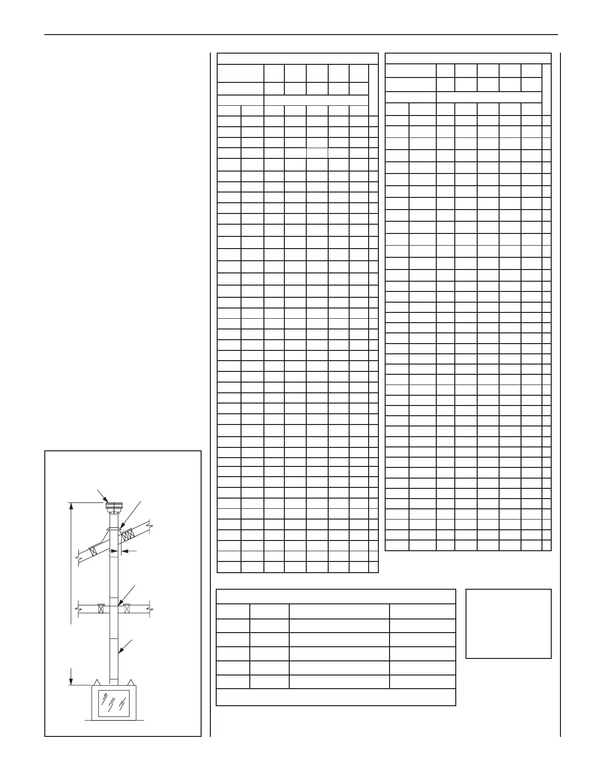
Figure 17
Vertical (Roof) Termination
Systems
This section includes configurations for vertical
(roof) termination systems with either straight
vertical venting (see below and Page 20) and
offset vertical venting (see Pages 18–20).
Secure Vent™ rigid vent pipe and termination
components are shown in the figures.
The tables on Page 20 summarize each sys-
tem’s minimum and maximum vertical and
horizontal length values.
For vertical (roof) termination, the minimum
vent height above the roof and/or adjacent
walls is specified in ANSI Z223.1, latest edi-
tion (in Canada, the current CAN/CSA-B149.1
installation code) and by major building
codes. Always consult your local codes for
specific requirements. A general guide to
follow is the Gas Vent Rule (see Figure 3B
on Page 8).
Vertical Termination System
with Straight Vertical Venting
Note: If not already done, install the pro-
vided vent restrictor before proceeding
(see Page 16).
Determine the number of straight vent sec-
tions required. Available straight vent sec-
tions (and their effective lengths) are listed
in Table 7, below. See Page 36 for all venting
components.
Plan the vent lengths so a joint does not occur
at the intersection of ceiling or roof joists.
Refer to the “VENT SECTION LENGTHS”
charts at right.
HSTGNELNOITCESTNEV
lanimoN
htgneLnoitceS
)sehcni(
621426384
T
O
T
A
L
Q
T
Y
noitceSteN
)sehcni(htgneL
2/1-42/1-012/1-222/1-432/1-64
tneVfothgieHsnoitceStneVforebmuN
sehcnitf
5.4573.0100001
957.0200002
5.01578.0010001
5152.1110002
5.91526.12100
0
3
1257.1020002
5.22578.1001001
5.52521.2120003
5.13526.2030003
5.43578.2000101
5.73521.3111003
5.34526.3021003
5457.3002002
5.64578.3000011
5.94521.4102003
1552.4100012
5.55526.4012003
7557.4001102
6652.5022004
5.76526.5003003
9657.5000202
276103004
5.37521.6100203
5.97526.6010203
1857.6000112
095.7021014
5.19526.
7002013
3957.7000022
698101204
5.79521.8100023
2015.8200024
5.301526.8000303
8019100304
4115.9020024
71157.9105006
5.811578.9110305
6215.01001304
5.031578.01101305
53152.11006006
8315.11000404
5.931526.11000033
5.241578.11100405
noitceSlanimoN
)sehcni(htgneL
621426384
T
O
T
A
L
Q
T
Y
noitceSteN
)sehcni(htgneL
2/1-42/1-012/1-222/1-432/1-64
tneVfothgieHsnoitceStneVforebmuN
sehcnitf
44121100034
0515.21010034
5.451578.21110035
5.061573.31020035
5.271573.41000505
77157.41100506
38152.51010506
6815.51000044
5.091578.51100045
5.691573.61010045
5.502521.71011507
70252.71000606
5.112526.71100607
5.712521.81010607
5.922521.91001607
5.232573.91000055
73257.91100056
5.142521.02000707
6425.02100708
25212010708
46222001708
67232000808
97252.32000066
5.082573.32100809
5.382526.32100
067
5.982521.42010067
5.103521.52001067
5.013578.52000909
5135.621009001
5.523521.72000077
0335.72100078
63382010078
54357.82000 01001
5.943521.92100 01011
27313000088
5.673573.13100089
5.973526.13000 11011
5.814578.43000099
32452.531000901
56457.8300000101
HSTGNELNOITCESTNEV
Firestop/Spacer
Termination
Flashing and
Storm Collar
Min. 1 in (25 mm)
Clearance to
Combustibles
Secure Vent
Vent Sections
(SV8L6, SV8L12,
SV8L24, SV8L36,
SV8L48)
Max. 60 ft
(18 m)
Min. 6 ft
(1.8 m)
Vertical Termination System
with Straight Vertical Venting
Metric
Conversion
Inches x 25.4 = mm.
Inches x 2.54 = cm.
Inches x 0.0254 = m.
INNOVATIVE HEARTH PRODUCTS • SEE-THROUGH DIRECT-VENT GAS FIREPLACES (DRT63STTEN/P) • INSTALLATION INSTRUCTIONS