24
NOTE: DIAGRAMS & ILLUSTRATIONS ARE NOT TO SCALE.
Example: If 20 feet of (H+H
1
)
horizontal vent run is needed,
then 10 feet minimum of (V)
vertical vent will be required.
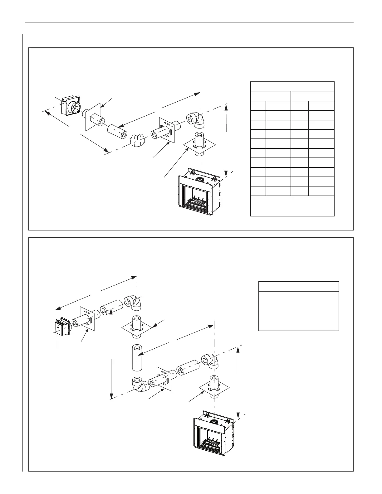
Figure 33: Horizontal Termination with Three 90-Degree Elbows
V
H
H
1
Horizontal Firestop/Spacer
(SV8HF4)
Vertical
Firestop/Spacer
(SV8BF)
Horizontal Firestop/Spacer
(SV8HF4)
V
H
H
1
V
1
Horizontal
Firestop/Spacer
(SV8HF4)
Vertical
Firestop/Spacer
(SV8BF)
Horizontal
Firestop/Spacer
(SV8HF4)
Vertical
Firestop/Spacer
(SV8BF)
Table D
H + H
1
max.
V min.
feet (meters) feet (meters)
3.5 (1.07) 2.5 (0.762)
6.5 (1.98) 3.5 (1.07)
8.5 (2.6) 4.5 (1.37)
10.5 (3.2) 5.5 (1.68)
12.5 (3.8) 6.5 (1.98)
14.5 (4.4) 7.5 (2.3)
16.5 (5.0) 8.5 (2.6)
18.5 (5.6) 9.5 (2.9)
20 (6.0) 10 (3.0)
V + H + H
1
= 40 ft (12.4 m) max.
H + H
1
= 20 ft (6.2 m) max.
Table E
H + H
1
= 20 ft (6.2 m) max.
V + V
1
+ H + H
1
= 40 ft (12.4 m) max.
V = 2.5 ft (0.762 m) min.
V + V
1
= 11 ft (3.35 m) min.
HORIZONTAL TERMINATION SYSTEM WITH HORIZONTAL/INCLINED RUN USING THREE 90-DEGREE ELBOWS
(Elbow connection not directly at appliance)
Note: The provided vent restrictor is required in all venting systems. See Page 16 for settings.
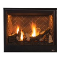
HORIZONTAL TERMINATION SYSTEM WITH HORIZONTAL/INCLINED RUN USING TWO 90-DEGREE ELBOWS
(Elbow connection not directly at appliance)
Note: The provided vent restrictor is required in all venting systems.
See Page 16 for settings.
INNOVATIVE HEARTH PRODUCTS • SEE-THROUGH DIRECT-VENT GAS FIREPLACES (DRT63STTEN/P) • INSTALLATION INSTRUCTIONS
HORIZONTAL VENT FIGURES/TABLES (continued)
Figure 32: Horizontal Termination with Two 90-Degree Elbows
See Table 8 on Page 23 as an aid in selecting venting
components for a particular range of exterior wall thicknesses.
See Table 8 on Page 23 as an aid in selecting venting
components for a particular range of exterior wall thicknesses.