NOTE:DIAGRAMS&ILLUSTRATIONARENOTTOSCALE.
13
Step 1.Followtheinstructionsbelowforthemodelyouareinstalling:
Model VRT2536WS:
Using a screwdriver remove the screw from the blower access panel
as shown in Figure 18. Slide the panel to the right until the flange
clears the opening. Remove the panel and set aside.
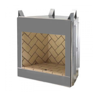
Models VRT3536WS, VRT3536WH, VRT3542WS & VRT3542WH:
Liftoutthebottomrefractorypanel(seeFigure 17).
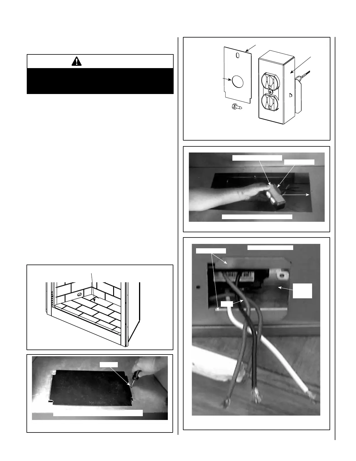
Step 2.Removetherectangularknock-out(forJ-Box)ontherightside
of unit (see Figure 8 for location). InstalltheJunctionBox&Electrical
outletbelowthereboxoorintotherectangularopeningontheright
side cabinet panel where you removed the knock-out (see Figures 20 &
21). The Junction Box / Electrical Kit is sold separately (see Page 15 for
ordering information).
• Squeeze the J-Box anges together to t into the opening shown in
Figures 20 and 21.
• Wires will need to be passed through the hole shown in Figure 19.
• An approved strain relief bushing (not supplied with the kit), is required
to restrain the wires (see Figure 19).
Step 3.Looselytieaknotinthepowercordtotakeupslack(seeFigure 22).
Step 4.LocatethetabsshowninFigure 23. Position the blower assembly
so that the tabs (located on the cabinet base) are seated in the notches of
the blower bracket. Bend the tabs over to secure the blower assembly (see
Figure 24).
Step 5. Plug power cord into the electrical outlet as illustrated in Figure 15.
Models: VRT3536WS,
VRT3536WH, VRT3542WS
& VRT3542WH
J-Box Flanges
J-Box &
Electrical
Outlet
Right Outside Cabinet Panel
Wires
Figure 17
Figure 20 -
Model VRT3542WS Shown
Figure 18 - Model VRT2536WS
Figure 21
Lift Out Bottom Refractory Panel
IMPORTANT
All electrical wiring must be performed by licensed Elec-
tricians. Electrical wiring must comply with the National
Electrical Code ANSI/ NFPA 70 - latest edition
Installation Instructions -
FBK-100orFBK200BlowerKitsandJBKJunctionBoxKit
Firebox
oor
Blower
Access
Panel
Remove screw, then lift out blower access panel.
J-Box Flange
Install into side wall rectanular opening
Firebox
oor
Screw
Figure 19 - Junction Box Kit (all models)
J-Box &
Receptacle
J-Box & Electrical Outlet
Screw
Remove knock-out
(strain relief bush-
ing [not supplied]
presses into this
hole around romex
wires - see Step 8 on
Page 14).
Cover Plate