NOTE:DIAGRAMS&ILLUSTRATIONARENOTTOSCALE.
14
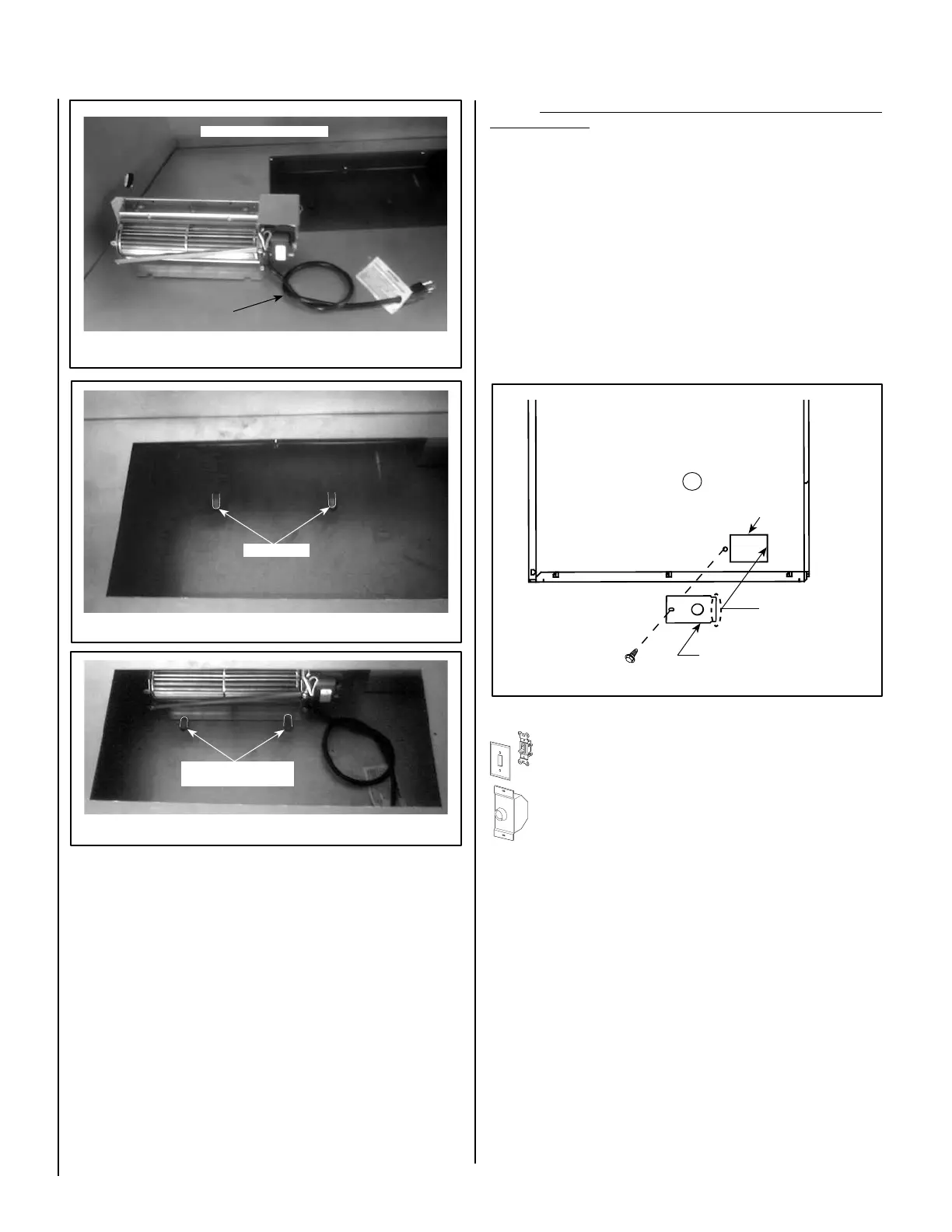
Step 8. Ensure that power supply wires are NOT "live" before making
these connections). Install J-Box Cover Plate as follows:
Feed the * Romex wires (or other equivalent plastic insulated
wire-ReferANSI/NFPA70-NationalElectricalCode-Latest
Edition)throughtheJ-BoxCoverretangularopening,thencon-
necttotheJ-boxwires.Thestrainreliefbushing(notsupplied)
shouldbepressedintotheknock-outonJ-boxcoveraroundthe
Romex(thiswillprovideprotectiontothewiresandpreventsstrain
againstconnectionsfromJ-box).SeeWiringDiagram-Figure
16. InstallthecoverplateoverJ-Boxopeningonapplianceas
shown in Figure 25.
Note:Wireconnectionsshouldbepositionedinsideoftheap-
pliance.
*Romexisaplasticinsulatedwirefrompowersupply-sometimescalled
non-metallic sheath.
Cabinet Base
Figure 22
Figure 21 -
VRT3542WS Shown
Figure 24 - VRT3542WS Shown
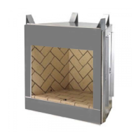
Loose knot in power
cord to take up slack
Firebox
oor
Model VRT3542WS Shown
Model VRT3542WS
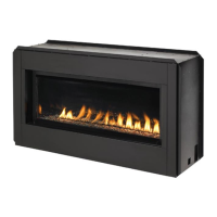
Locating Tabs
Bend Locating Tabs Over
(into notches)
Use screw provided and
secure in place as shown
The notched side of
cover plates goes inside
firebox panel
Screw
Cover Plate
Right Side Panel of Firebox
Figure 25 - Installing J-box Cover Plate - All Models
Step 9.Followtheinstructionsbelowforthekityouareinstalling:
FBK-100Kits-Installaeld-provided(orP/N85L87)ON/OFFwall
switch in a convenient location on a wall, near the fireplace.
FBK-200Kits-Installthekit-providedvariablespeedcontrol(rheo-
stat) in a convenient location on a wall, near the fireplace.
Step 10.Followtheinstructionsbelowforthemodelyouareinstalling:
Model VRT2536WS:
Reinstall the blower access panel that was removed on Step 1 (see
Figure 18).
Models VRT3536WS, VRT3536WH, VRT3542WS & VRT3542WH:
Reinstall the bottom refractory panel that was removed on Step 1
(see Figure 17).
J-Box opening
on appliance
Step 6. Routea3-wire,120VAC,60Hz,1phpowersupplytotheright
side of appliance.
Step 7.LocatetheJ-Boxcover(providedinJ-BoxKit).Removetheround
knock-out (see Figure 19).