vi
Table of Contents
Preface
Chapter 1 Introduction
1-1 Overview ......................................................................................................... 1-1
1-2 Processor Overview ..................................................................................... 1-10
1-3 Special Features ............................................................................................1-11
1-4 PC Health Monitoring .....................................................................................1-11
1-5 ACPI Features ............................................................................................... 1-12
1-6 Power Supply ................................................................................................ 1-12
Chapter 2 Installation
2-1 Standardized Warning Statements ................................................................. 2-1
2-2 Static-Sensitive Devices .................................................................................. 2-4
2-3 Memory Support .............................................................................................. 2-5
2-4 Motherboard Installation .................................................................................. 2-8
2-5 Connectors/IO Ports ...................................................................................... 2-10
Backplane I/O Panel ..................................................................................... 2-10
Serial Ports ................................................................................................2-11
Ethernet Ports ...........................................................................................2-11
Universal Serial Bus (USB) ...................................................................... 2-12
Unit Identier Switch ................................................................................ 2-13
VGA .......................................................................................................... 2-13
Front Control Panel ....................................................................................... 2-14
Front Control Panel Pin Denitions............................................................... 2-15
NMI Button ............................................................................................... 2-15
Power LED .............................................................................................. 2-15
HDD LED .................................................................................................. 2-16
NIC1/NIC2 (LAN1/LAN2) .......................................................................... 2-16
Overheat (OH)/Fan Fail/PWR Fail/UID LED ............................................ 2-17
Power Fail LED ........................................................................................ 2-17
Reset Button ........................................................................................... 2-18
Power Button ........................................................................................... 2-18
2-6 Connecting Cables ........................................................................................ 2-19
ATX PWR, DC PWR and HDD PWR Connectors (JPW1, J1, J3) .......... 2-19
Fan Headers (Fan 1 ~ Fan 3) .................................................................. 2-20
Chassis Intrusion (JL1) ........................................................................... 2-20
Internal Buzzer (SP1) ............................................................................... 2-21
Power LED/Speaker ................................................................................. 2-21
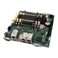
A1SAi & A1SRi Series Motherboard User’s Manual
 Loading...

