42
Super C9Z490-PG/-PGW User's Manual
2.8 Connectors
This section provides brief descriptions and pinout denitions for onboard headers and
connectors. Be sure to use the correct cable for each header or connector.
Power Connections
ATX Power Supply Connector
The 24-pin power supply connector (JPW1) meets the ATX SSI EPS 12V specication. You
must also connect the 8-pin (JPW2) processor power connector to the power supply.
ATX Power 24-pin Connector
Pin Denitions
Pin# Denition Pin# Denition
13 +3.3V 1 +3.3V
14 -12V 2 +3.3V
15 Ground 3 Ground
16 PS_ON 4 +5V
17 Ground 5 Ground
18 Ground 6 +5V
19 Ground 7 Ground
20 Res (NC) 8 PWR_OK
21 +5V 9 5VSB
22 +5V 10 +12V
23 +5V 11 +12V
24 Ground 12 +3.3V
Required Connection
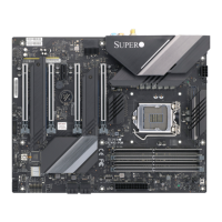
1. JPW1
PCH
PLX
Super I/O
LAN Controller
SW1
(CLEAR CMOS)
10G LAN
Controller
+
+
3
1
DESIGNED IN USA
C9Z490-PGW
REV:1.01
BIOS
LICENSE
MAC CODE
MAC CODE
BAR CODE
MH14
JRLED1
MH11
MH10
MH12
MH13
MH15
JSTBY1
JTPM1
HD AUDIO
B1
SP1
JD1
JSD1
SYS_FAN3
USB10/11 (3.2(5Gb))
JPW1
LED18
LED17
LED3
LED2
LED1
JPW2
JI2C2
JI2C1
JL1
LED4
JPAC1
JLED1
JWD1
JPME2
12V_PUMP_PWR1
USB9 (3.2(20Gb))
USB8 (3.2(10Gb))
USB2/3
JF1
BOOT LED
VGA LED
DIMM LED
CPU LED
DP/HDMI
LAN1
AUDIO FP
COM1
USB0/1
PCIE M.2-M1
CPU SLOT1 PCI-E 3.0 X8 (IN X16)
CPU SLOT3 PCI-E 3.0 X16
PCH SLOT4 PCI-E 3.0 X1
CPU SLOT5 PCI-E 3.0 X8 (IN X 16)
I-SATA1
I-SATA0
I-SATA3
I-SATA2
CPU SLOT7 PCI-E 3.0 X16
SYS_FAN2
PCIE M.2-M2
USB12 (3.2(10Gb))
USB6/7 (3.2(10Gb)) USB4/5 (3.2(5Gb))
POWER
BUTTON
DIMMB1
DIMMB2
DIMMA1
DIMMA2
RESET
BUTTON
SYS_FAN1
CPU_FAN1
CLEAR CMOS
CPU_FAN2
LAN2
PCIE M.2-E1
WiFi+BT
1
 Loading...
