Do you have a question about the Supermicro C2SBM-Q and is the answer not in the manual?
Introduces the Supermicro motherboard, its design, and quality standards.
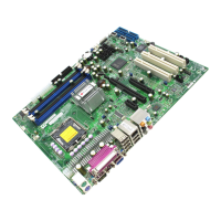
Illustrates the physical layout of components and connectors on the motherboard.
Warns about potential system instability and damage from overclocking.
Provides a quick reference for motherboard jumpers, connectors, and their functions.
Details the supported Intel Core 2 Duo/Quad processors and related technologies.
Describes memory support, including type, speed, capacity, and dual-channel operation.
Lists the Intel Q35 GMCH and ICH9DO chipset features and capabilities.
Explains onboard voltage and fan monitoring capabilities for system health.
Lists onboard controllers for SATA, serial ports, Ethernet, audio, and VGA.
Presents a diagram illustrating the system's major components and their interconnections.
Details the GMCH's role in memory, graphics, and PCI-Express interface.
Lists I/O functions and PCI devices supported by the ICH9DO controller.
Describes the feature allowing remote system power-up via LAN.
Provides precautions to prevent ESD damage to components.
Guides on how to mount the motherboard into the chassis.
Details the procedure for installing the CPU and its heatsink.
Step-by-step instructions for installing the LGA 775 processor into the socket.
Step-by-step instructions for mounting the CPU heatsink and fan.
Guides on installing RAM modules into the motherboard slots.
Step-by-step instructions for inserting DIMM modules into slots.
Details memory specifications, including type, speed, and dual-channel support.
Describes front and back panel connectors and I/O ports.
Lists and defines the I/O ports on the motherboard's back panel.
Provides general procedures for diagnosing system issues.
Outlines steps to diagnose and resolve 'no power' issues.
Provides steps to diagnose and resolve 'no video' issues.
Lists steps to diagnose and resolve memory-related errors.
Configures boot devices and their priority order.
Manages the sequence and inclusion of bootable devices.
Describes errors related to fixed disk identification and configuration.
Indicates a dead CMOS battery requiring replacement and setup.
Indicates corrupted CMOS data, using default configuration.
Indicates a problem with NVRAM (CMOS) data.
Indicates the operating system could not be located.
Reports parity error in the system bus, indicating data corruption.
Reports parity error in the I/O bus, indicating data corruption.
Provides a list of POST codes and their corresponding descriptions.
Instructions for installing motherboard drivers and utilities.
| Brand | Supermicro |
|---|---|
| Model | C2SBM-Q |
| Category | Motherboard |
| Language | English |
