A. GLAN1
B.
Speaker/Buzzer
Speaker
A Speaker/Buzzer header (J9) is
located on the motherboard. See
the table on the right for speaker pin
definitions.
Note: The speaker connector
pins are for use with an external
speaker. If you wish to use the
onboard speaker, you should
close pins 3-4 with a jumper.
GLAN 1 (Gigabit Ethernet
Port)
A G-bit Ethernet port is located at J11
on the IO backplane. This port accepts
RJ45 type cables.
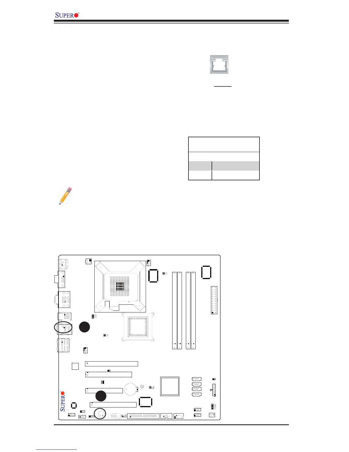
Speaker Connector
(J9)
Pin Setting Definition
Pins 3-4 Internal Speaker
Pins 1-4 External Speaker
GLAN1
A
B