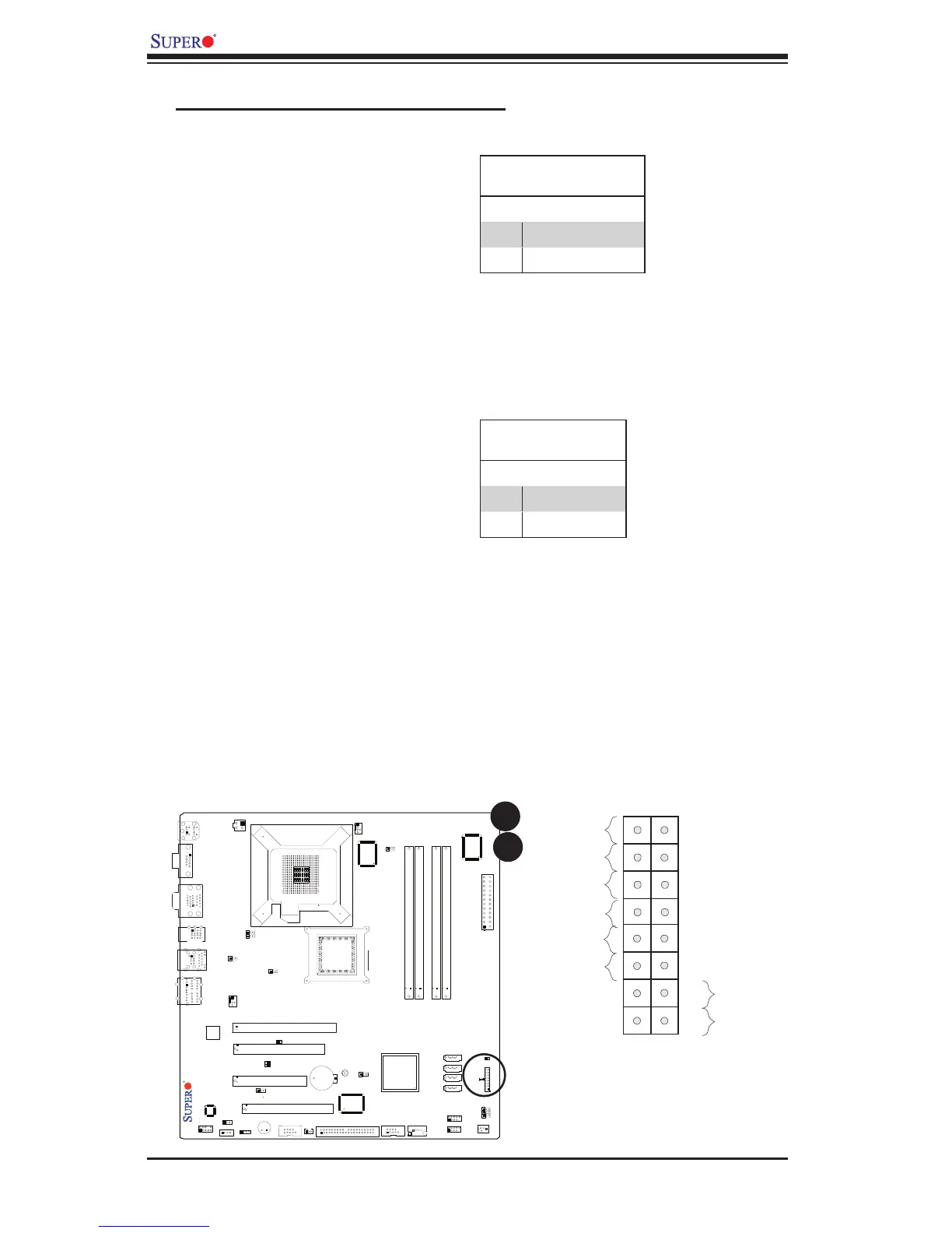
EasyManuals Logo

Supermicro C2SBM-Q User Manual

Supermicro C2SBM-Q
90 pages
To Next Page IconTo Next Page
To Previous Page IconTo Previous Page
Page #28 background imageLoading...
Page #28 background image
2-10
C2SBM-Q User's Manual
FAN1
JI2C2
JWOR
JFSB3
JF1
JWD
JLED
Battery
J40
DIMM1A
DIMM2A
DIMM1B
I-SATA2
I-SATA3
SPEAKER
KB/MOUSE
CPU Fan
J28
VGA
JGS1
USB
2/3/4/5
J43
J11
USB 0,1
J46
Audio
J41
4-Pin PWR
LGA 775 CPU
JFSB2
JFSB1
PCI2
Slot5 PCI-E x4
JPAC
J9
Buzzer
SPKR
Slot4 PCI-33MHz
PCI1
J12
J3
IDE#1
J45
FP USB 8/9
FP USB 6/7
J44
JL1
LE1
FP CTRL
Intel Q35
24-pin ATX PWR
Audio CTRL
CD-IN
CD1
Front Audio
W83627DHG
S I/O 1
IDE CTRL
ITE 8213
J
1
5
C
O
M
4
USB 10
JWOL
I-SATA0
I-SATA1
JS4
JS3
JS1
JS2
FAN2
Fan3
JPUSB1
PCI3
Slot7 PCI-E x16
JI2C1
JP2
Intel ICH9DO
JPUSB2
J47
JPL1
COM2
W83627DHG
S I/O 2
J14
COM3
Slot6 PCI-33MHz
PCI1
JPT1
DIMM2B
LAN CTRL
LAN 1
C2SBM-Q
COM1
J31
JBT1
Power LED
The Power LED connection is located
on pins 15 and 16 of JF1. Refer to the
table on the right for pin definitions.
Power LED
Pin Definitions (JF1)
Pin# Definition
15 LED_Anode+
16 PWR LED Signal
3. Front Control Panel Pin Definitions
A. PWR LED connector
B. HDD LED connector
HDD LED
The HDD LED connection is located
on pins 13 and 14 of JF1. Attach a
hard drive LED cable here to display
disk activity (for any hard drives on
the system, including SAS and Serial
ATA). See the table on the right for
pin definitions.
HDD LED
Pin Definitions (JF1)
Pin# Definition
13 LED_Anode+
14 HD Active
Header Pins
A
B

Table of Contents

Questions and Answers:

Question and Answer IconNeed help?

Do you have a question about the Supermicro C2SBM-Q and is the answer not in the manual?

Supermicro C2SBM-Q Specifications

General IconGeneral
BrandSupermicro
ModelC2SBM-Q
CategoryMotherboard
LanguageEnglish

Related product manuals