Front Panel Audio Control
When front panel headphones are
plugged in, the back panel audio output
is disabled. This is done through the FP
Audio header (J12). If the front panel
interface card is not connected to the front
panel audio header, jumpers should be
installed on the header (J12) pin pairs:
1-2, 5-6, and 9-10. If these jumpers are
not installed, the back panel line out
connector will be disabled and microphone
input Pin 1 will be left floating, which can
lead to excessive back panel microphone
noise and cross talk. See the table below
for pin definitions.
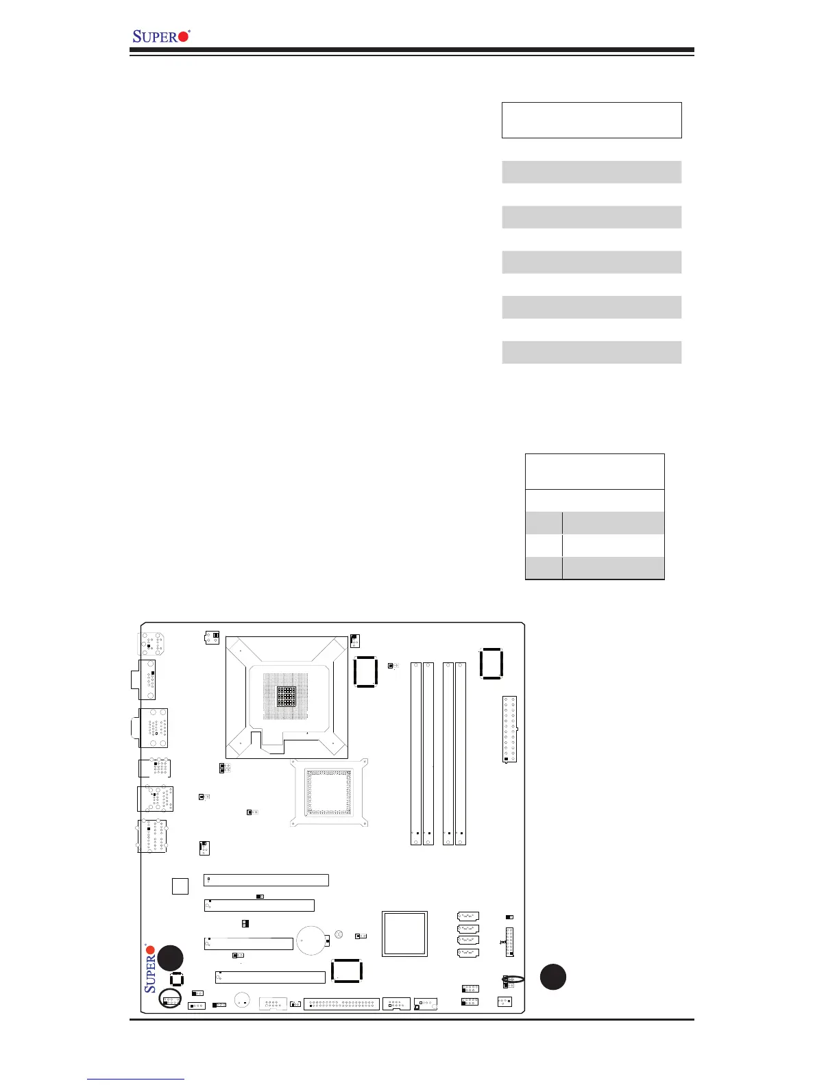
A. Front Panel Audio
B. PWR LED
Power LED
The Power LED connector is designated
JLED. This connection is used to pro-
vide LED Indication of power supplied to
the system. See the table on the right
for pin definitions.
PWR LED
Pin Definitions
Pin# Definition
1 +5V
2 Key
3 Ground
High Definition Front Panel
Audio
Pins# Signal
1 MC_L
2 AUD_GND
3 MC_R
4 FP_Audio-Detect
5 Line_2_R
6 Ground
7 FP_Jack-Detect
8 Key
9 Line_2_L
10 Ground
B
A