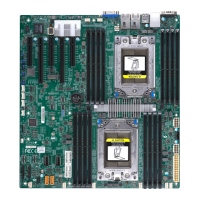
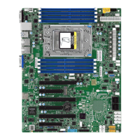
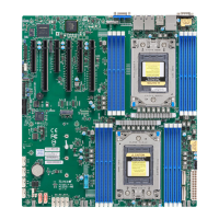
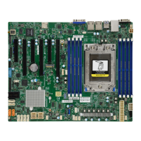
11
Chapter 1: Introduction
Quick Reference Table
Jumper Description Default Setting
JBT1 CMOS Clear Open (Normal)
UID SW Unit ID Switch (Push-Button Toggle Switch ON/OFF) O
JPG1 VGA Enable Pins 1-2 (Enabled)
JWD1 Watch Dog Control Pins 1-2 (Reset)
JUBUD1 BIOS Update O
LED Description Status
LED1 Unit Identier (UID) LED Blue: UID Indentied
LED4 Onboard Power LED Solid Green: Power On
LEDM1 BMC Heartbeat LED
Green: Blinking (BMC Normal)
Green: Fast Blinking (BMC Initializing)
LEDM21~LEDM22 M.2 SSD LED Blinking: Device Working
Connector Description
JL1 Chassis Intrusion Header
SATA0-1, SATA2-3 Dual SATA Port Connectors Supporting up to Four Devices
J4901 Front Panel HD Audio Header
JPW2 12V 8-pin CPU Core Power Supply Connector
JPW1 24-pin ATX Main Power Connector (Required)
JF1 Front Control Panel Header
BT1 Onboard Battery
M.2-C1/M.2-C2 M.2 PCIe Interfaces
JSTBY1 Inject External P5V_STBY Power
JIPMB1 4-pin BMC External I
2
C Header (For an IPMI-Supported Card)
DIMMA1~DIMMB2 DIMM Slots
FAN1~FAN5 CPU Fans
FANA~FANB System Cooling Fans
BMC LAN BMC LAN Port
JTPM1 TPM (Trusted Platform Module)/Port 80
JPI2C1 Power System Management Bus (SMB) I
2
C Header
COM1/COM2 Serial Port/Header
VGA Rear Panel VGA Port
USB0/1 USB 2.0 Ports
USB2/4 Rear USB 3.2 Gen1 Alt Ports
USB3/5/7 Rear USB 3.2 Gen2 Ports
USB6 USB3.2 Gen2x2 Port
USB8/9 Front USB 3.2 Gen1 Ports
Note: Jumpers, connectors, switches, and LED indicators that are not described in the
preceding tables are for manufacturing testing purposes only, and are not covered in this
manual.

 Loading...

