45
Chapter 2: Installation
Power SMB Header (PWRI
2
C)
Power System Management Bus (I
2
C) header monitors power supply, fan and system
temperatures. See the table below for pin denitions.
Power SMB Header
Pin Denitions
Pin# Denition
1 Clock
2 Data
3 PWR Fail
4 Ground
5 +3.3V
Overheat LED/Fan Fail (JOH1)
The JOH1 header is used to connect an LED indicator to provide warnings of chassis
overheating or fan failure. This LED will blink when a fan failure occurs. Refert to the table
on right for pin denitions.
Overheat/Fan Fail
Pin Denitions
Pin# Denition
1 5vDC
2 OH Active
Overheat / Fan Fail
LED Status
Status Denition
O Normal
On, Solid Overheat
On, Blinking Fan Failure
SATA (SATA8~15)
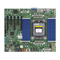
The H13SSL-N/NT has eight available SATA 3.0 ports (SATA10 and SATA11).
SATA Connectors
Pin Denitions
Pin# Signal
1 Ground
2 SATA_TXP
3 SATA_TXN
4 Ground
5 SATA_RXN
6 SATA_RXP
7 Ground
 Loading...


