USB11
DIMM2B
DIMM2A
USB2/3
Slot6 PCI-E 2.0 x8
JF1
I-SATA2
Slot4 PCI-E 2.0 x4 on x8
KB/MOUSE
DIMM1B
DIMM1A
CPU
Slot7 PCI-E 2.0 x8
BIOS
B1
Battery
PHY
BMC
CTRL
82574L
S I/O
T-SGPIO2
FP CTRL
Cougar Point
Standard PCH
Memory Chip
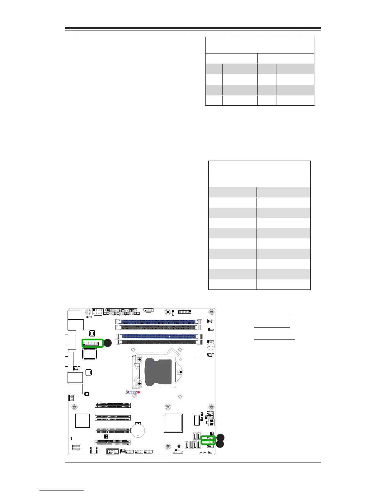
X9SCM/X9SCL(-F) Rev.1.0
Fan4
PHY
82579
PHY
(For X9SCM only)
(*I-SATA 0/1:
X9SCL: SATA2, X9SCM: SATA3)
Socket H2
LGA 1155
CPU
I-SATA4
I-SATA5
I-SATA3
I-SATA1
I-SATA0
Slot5 PCI-E 2.0 x4 on x8
USB/0/1
LAN1
LAN2
LE7
JPME1
JPME2
LE4
C
Trusted Platform Module Header
Pin Denitions
Pin # Denition Pin # Denition
1 LCLK 2 GND
3 LFRAME 4 No Pin
5 LRESET 6 VCC5
7 LAD3 8 LAD2
9 VCC3 10 LAD1
11 LAD0 12 GND
13 RSV0 14 RSV1
15 SB3V 16 SERIRQ
17 GND 18 CLKRUN
19 LPCPD 20 RSV2
Serial_Link-SGPIO
Pin Denitions
Pin# Denition Pin Denition
1 NC 2 NC
3 Ground 4 DATA Out
5 Load 6 Ground
7 Clock 8 NC
T-SGPIO 0/1 Headers
Two T-SGPIO (Serial-Link General
Purpose Input/Output) headers are
located near the SATA connectors
on the motherboard. These headers
are used to communicate with the
enclosure management chip in the
system. See the table on the right
for pin denitions. Refer to the board
layout below for the locations of the
headers.
NC: No Connections
A. T-SGPIO 0
B. T-SGPIO 1
C. TPM Header
A
B
TPM Header
This header is used to connect a
Trusted Platform Module (TPM), which
is available from a third-party vendor.
A TPM is a security device that sup-
ports encryption and authentication
in hard drives. It enables the moth-
erboard to deny access if the TPM
associated with the hard drive is not
installed in the system. See the table
on the right for pin denitions.
 Loading...