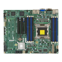
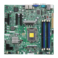
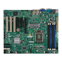
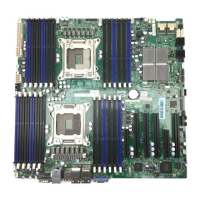
vii
Table of Contents
Removing Memory Modules ........................................................................... 2-8
Memory Support .............................................................................................. 2-9
Memory Population Guidelines ..................................................................... 2-10
2-4 Motherboard Installation .................................................................................2-11
Tools Needed .................................................................................................2-11
Location of Mounting Holes ...........................................................................2-11
Installing the Motherboard ............................................................................ 2-12
2-5 Connectors/IO Ports ...................................................................................... 2-13
Motherboard I/O Backpanel .......................................................................... 2-13
ATX PS/2 Keyboard/Mouse Ports ............................................................ 2-14
Universal Serial Bus (USB) ...................................................................... 2-15
Ethernet Ports .......................................................................................... 2-16
Serial Ports ............................................................................................... 2-17
Video Port ................................................................................................. 2-18
Front Control Panel ....................................................................................... 2-19
FrontControlPanelPinDenitions............................................................... 2-20
Power LED .............................................................................................. 2-20
HDD LED .................................................................................................. 2-20
Power Fail LED ........................................................................................ 2-20
NIC1/NIC2 (LAN1/LAN2) .......................................................................... 2-21
Overheat (OH)/Fan Fail / UID LED .......................................................... 2-21
NMI Button ............................................................................................... 2-22
Reset Button ........................................................................................... 2-22
Power Button ........................................................................................... 2-22
2-6 Connecting Cables & Optional Devices ........................................................ 2-23
ATX Main PWR (JPW1) & CPU PWR Connectors (JPW2) ..................... 2-23
Fan Headers (FAN1~4, FANA) ................................................................ 2-24
Chassis Intrusion (JL1) ............................................................................ 2-24
Speaker (JD1) .......................................................................................... 2-25
Internal Buzzer (SP1) ............................................................................... 2-25
Wake-On-LAN (JSTBY1) .......................................................................... 2-25
Power Supply I
2
C (JPI2C1) ...................................................................... 2-26
DOM PWR Connector (JSD1) .................................................................. 2-26
T-SGPIO 1/2 & 3-SGPIO 1/2 Headers ..................................................... 2-27
TPM Header (JTPM1) .............................................................................. 2-27
Unit ID Switch (UID SW) .......................................................................... 2-28
Overheat/Fan Fail LED (JOH1) ........................................................ 2-28
System Management Bus (JIPMB1) .................................................2-29

 Loading...
