5150
Chapter 4: Motherboard ConnectionsSuperServer 5019P-WT/WTR User's Manual
4.3 Ports and Headers
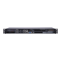
Rear I/O Ports
of the motherboard.
Figure 4-2. Rear I/O Ports
# Description # Description
1. COM Port 1 6. USB7 (3.0)
2. Dedicated IPMI LAN 7. LAN1
3 USB1 (2.0) 8 LAN2
4 USB0 (2.0) 9 VGA Port
5. USB8 (3.0) 10 UID Switch
1
9
876
5
4
3
2
10
Power LED
The Power LED connection is located on pins 15 and 16 of JF1. Refer to the table below
Power LED
Pin Denitions (JF1)
Pins Denition
15 3.3V
16 Ground
NMI Button
The non-maskable interrupt button header is located on pins 19 and 20 of JF1. Refer to the
NMI Button
Pin Denitions (JF1)
Pins Denition
19 Control
20 Ground
VGA Port
The onboard VGA port is located next to LAN Port 2 on the I/O back panel. Use this connection
for VGA display.
LAN Ports
Two 10 Gigabit Ethernet ports (LAN1, LAN2) are located on the I/O back panel. In addition,
a dedicated IPMI LAN is located above USB ports 0/1 on the back panel. All of these ports
accept RJ45 type cables. Please refer to the LED Indicator section for LAN LED information
COM Port
There is one COM port (COM1) on the I/O back panel and one COM header (COM2) on the
Unit Identier Switch/UID LED Indicator
switch is located at JUIDB1, which is next to the VGA port on the back panel. The UID LED
(LE1) is located next to the UID switch. When you press the UID switch, the UID LED will
be turned on. Press the UID switch again to turn off the LED indicator. The UID Indicator
Note: UID can also be triggered via IPMI on the motherboard. For more information on IPMI,
please refer to the IPMI User's Guide posted on our website at http://www.supermicro.com.
UID Switch
Pin Denitions
Pin# Denition
1 Ground
2 Ground
3 Button In
4 Button In
UID LED
Pin Denitions
Color Status
Blue: On
 Loading...
