52
X11SCA/-W/-F User Manual
M.2 Connection
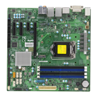
The X11SCA/-W/-F board contains three M.2 connectors, one of which supports Wi+BT
(on back panel). M.2, formerly Next Generation Form Factor (NGFF), serves to replace mini
PCI-E and mSATA. M.2 allows for a greater variety of card sizes, increased functionality, and
spatial efciency. The M.2 sockets support 3.0 x4 (32 Gb/s) card in 2260, 2280, and 22110
form factors.
Note: If using an M.2 device with a lower thermal tolerance, a heat sink should be
installed on the top of the M.2 device and the device should be set to "boot up device"
(refer to BIOS section).
1. M.2 Connector 1
2. M.2 Connector 2
3. M.2 Connector 3
(X11SCA-W only)
4. Onboard Power LED
Header
1
Onboard Power LED Header
An onboard Power LED header is located at JLED1. This Power LED header is connected to
the Front Control Panel located at JF1 to indicate the status of system power. See the table
below for pin denitions.
Onboard Power LED
Pin Definitions
Pin# Denition
1 VCC
2
Connection to
PWR LED on JF1
3
Connection to
PWR LED on JF1
2
3
4
 Loading...
