38
X11SSH-CTF/TF User's Manual
Power Button
OH/Fan Fail
NIC1 Active LED
Reset Button
HDD LED
PWR LED
Reset
PWR
3.3V
ID_UID_SW/3.3V Stby
3.3V Stby
Ground
19
X
Ground
X
3.3V Stby
3.3 V
5V Stby
20
1 2
Ground
Power Fail LED
NIC2 Active LED
NMI
DESIGNED IN USA
X11SSH-TF
REV:1.01
BAR CODE
SAS CODE
MEGERAC
LICENSE
IPMI CODE
MAC CODE
PRESS FIT
Intel
PCH
LSI3008
(-CTF only)
X550
BT1
JSAS1
JSTBY1
LEDS1
J2
SP1
LE1
LEDBMC
LEDPWR
JPSAS1
JOH1
JL1
JPG1
JBR1
JVRM2
JVRM1
JPME2
JVR1
JPS1
JPB1
JI2C1
JI2C2
JWD1
JPTG1
JSD2
JSD1
FAN5
FANA
FAN3
FAN4
FAN1
FAN2
JUIDB1
JIPMB1
JPI2C1
JD1
JPWR2
I-SGPIO2
I-SGPIO1
I-SATA7
I-SATA6
I-SATA3
I-SATA2
I-SATA1
I-SATA0
JF1
JTPM1
JPWR1
I-SATA5
I-SATA4
MH8
J24
LE3
JBT1
JPCK1
DIMMB2
DIMMB1
DIMMA2
DIMMA1
USB8(3.0)
USB4/5
USB9/10(3.0)
USB2/3
CPU Socket LGA1151
PCH SLOT4 PCI-E 3.0 X2 (IN X4)
CPU SLOT6 PCI-E 3.0 X8
VGA
LAN2
LAN1
USB6/7
(3.0)
USB0/1
IPMI_LAN
COM2
COM1
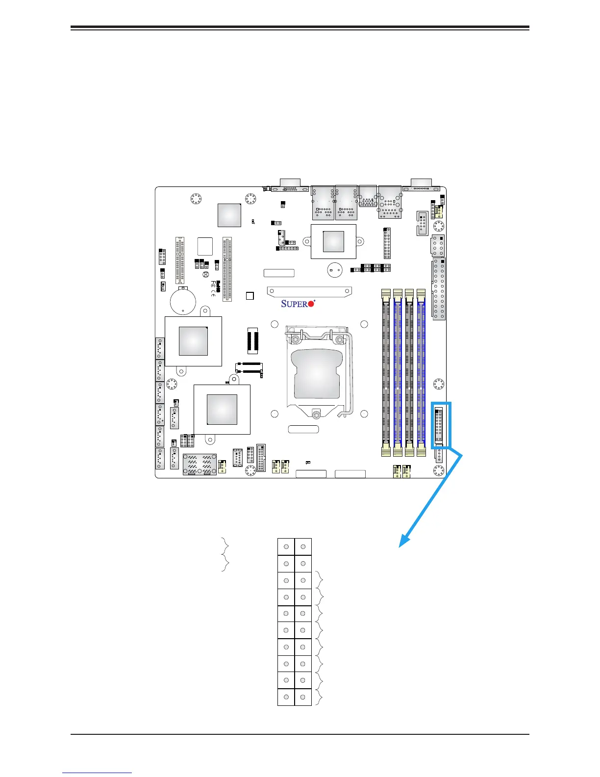
Figure 2-3. JF1 Header Pins
2.6 Front Control Panel
JF1 contains header pins for various buttons and indicators that are normally located on a
control panel at the front of the chassis. These connectors are designed specically for use
with Supermicro chassis. See the gure below for the descriptions of the front control panel
buttons and LED indicators.