13
Chapter 1: Introduction
Note: Table is continued on the next page.
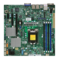
Quick Reference Table
Jumper Description Default Setting
JBR1 BIOS Recovery Pins 1-2 (Normal)
JBT1 CMOS Clear Open (Normal)
JI
2
C1/JI
2
C2 SMB to PCI-E Slots Enable/Disable Pins 2-3 (Disabled) (Default)
JPB1 BMC Enabled Pins 1-2 (Enabled)
JPCK1 LANCONF Flash Pins 2-3 (Disabled) (Default)
JPG1 VGA Enable/Disable Pins 1-2 (Enabled)
JPME2 Manufacturing Mode Pins 1-2 (Normal)
JPS1 SAS 3.0 Enable/Disable (X11SSH-CTF only) Pins 1-2 (Enabled)
JPSAS1 SAS HDD Enable/Disable (X11SSH-CTF only) Pins 1-2 (Enabled) (Default)
JPTG1 10Gb LAN Enable/Disable Pins 1-2 (Enabled)
JVRM1 VRM SMB Clock (to BMC or PCH) Pins 1-2 (BMC, Normal)
JVRM2 VRM SMB Data (to BMC or PCH) Pins 1-2 (BMC, Normal)
JWD1 Watch Dog Pins 1-2 (Reset)
LED Description Status
LEDBMC BMC Heartbeat LED Blinking Green: BMC Normal
LEDPWR Onboard Power LED Solid Green: Power On
LEDS1 SAS Activity LED (X11SSH-CTF only) Blinking Green: SAS Active, Red: SAS Error
LE1 UID LED Solid Blue: Unit Identied
LE3 M.2 LED Blinking Green: Active
Connector Description
BT1 Onboard Battery
COM1/COM2 COM Port/COM Header
FAN1 ~ FAN5, FANA System/CPU Fan Headers (FAN1: CPU Fan)
IPMI_LAN Dedicated IPMI LAN Port
I-SATA0 ~ I-SATA7 Intel® PCH SATA 3.0 Ports
I-SGPIO1/I-SGPIO2 Serial Link General Purpose I/O Headers
J24 M.2 PCI-E 3.0 X4 Slot
JD1 Power LED/Speaker Header (Pins 1-3: Power LED, Pins 4-7: Speaker)
JF1 Front Control Panel Header
JIPMB1 4-pin BMC External I2C Header (for an IPMI Card)
JL1 Chassis Intrusion Header
JOH1 Overheat LED Header
JPI
2
C1 Power Supply SMBbus I
2
C Header
JPWR1 24-pin ATX Power Connector
JPWR2 12V 8-pin Processor Power Connectors
JSAS1 Eight SAS 3.0 Ports (X11SSH-CTF only)